Pneumatic fuse terminal crimping mold

A technology for crimping dies and terminals, applied in the direction of connection, electrical components, circuits, etc., can solve problems such as low efficiency, unstable crimping quality, and inability to ensure crimping consistency, achieve stable feeding, and prevent unstable feeding. , the effect of stable crimping state

Active Publication Date: 2014-07-02
HEBI HAICHANG SPECIAL EQUIP +1
View PDF3 Cites 9 Cited by
  • Summary
  • Abstract
  • Description
  • Claims
  • Application Information

AI Technical Summary

Problems solved by technology

This method is inefficient, the quality of crimping is unstable, and the consistency of crimping cannot be guaranteed

Method used


Image

  • Pneumatic fuse terminal crimping mold
  • Pneumatic fuse terminal crimping mold
  • Pneumatic fuse terminal crimping mold

Examples


Embodiment Construction

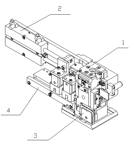
[0021] Such as figure 1 As shown, a pneumatic crimping die for a fuse terminal includes a hanger assembly 1 , a feeding assembly 2 , a mold base assembly 3 and a feeding base assembly 4 . The slide block 3-2 in the hanging head assembly and the formwork assembly is connected together by screws, and the slide block 3-2 in the formwork assembly is fixed on the side of the formwork 3-11 by the left pressing plate 3-19 and the right pressing plate 3-20. In the groove, the feeding assembly mounting plate 2-3 in the feeding assembly is connected together with the mold base 3-11 in the mold base assembly by screws, and the feeding bottom plate assembly is connected with the base plate spacer 3-15 in the mold base assembly by screws. Together, and a screw is connected to the mold base 3-11 in the mold base assembly through the through hole in the feeding base plate 4-3, through which the front and rear positions of the feeding base plate assembly can be adjusted to achieve the pur...


PUM


Abstract

A pneumatic fuse terminal crimping mold comprises a head hanging assembly, a material feeding assembly, a mold base assembly and a material-feeding bottom plate assembly. The head hanging assembly is connected with a sliding block in the mold base assembly; the sliding block in the mold base assembly is fixed in a groove of a mold base by a left pressing plate and a right pressing plate; a material feeding assembly mounting plate in the material feeding assembly is connected with the mold base in the mold base assembly; the material-feeding bottom plate assembly is connected with a bottom plate cushion block in the mold base assembly through screws; and the screws are connected to the mold base in the mold base assembly through via holes in the material-feeding bottom plate assembly. The pneumatic fuse terminal crimping mold has the following beneficial effects: a double-guide-rod pneumatic material feeding structure is adopted, material feeding is stable, and the requirement on terminals of different step pitches and different numbers of terminals in different groups can be met; a terminal is positioned by using a positioning claw and a material pressing block and can be effectively prevented from being deformed during the crimping process; a material feeding claw starts to draw back only after the positioning claw tightly presses the terminal, thus effectively preventing instable material feeding caused by withdrawal of the material feeding claw; and an inclined material cutting method makes a cut edge of the terminal smaller and neater.

Description

technical field [0001] The patent of the present invention relates to a crimping die for crimping chain-type safety terminals. This crimping die makes the crimping quality stable after crimping chain-type safety terminals. After the crimped safety terminals are installed in the sheath There will be no quality accidents caused by the contact of several groups of safety terminals with each other, and the original step distance of the terminals will not be changed. Background technique [0002] The insurance terminal on the car (such as Molex's 35413-6202) can ensure the safety of people and cars after the car wiring harness fails. This type of terminal is generally cut off in multiple groups and then crimped. However, the crimping of this type of terminal has always troubled various wire harness manufacturers, because the step distance of this type of terminal is small, the terminals are closely arranged, the material tape is behind the crimping part of the leather wire, and t...

Claims


Application Information

Patent Timeline
Patent Type & Authority Applications(China)
IPC IPC(8): H01R43/055
Inventor 胡建华郭得岁易红建孙强
Owner HEBI HAICHANG SPECIAL EQUIP
Why Eureka
Try Eureka