Combined type counteractive fly wheel

A reaction flywheel, composite technology, applied in the flywheel field, can solve the problems of speed saturation, reaction flywheel failure, etc., to delay the phenomenon of flywheel speed saturation and improve controllability

Active Publication Date: 2014-07-02
BEIJING UNIV OF TECH
View PDF7 Cites 5 Cited by
  • Summary
  • Abstract
  • Description
  • Claims
  • Application Information

AI Technical Summary

Problems solved by technology

The reaction torque generated by the conventional reaction flywheel is proportional to its rotational angular acceleration and has nothing to do with the rotation speed of the reaction flywheel. The speed saturation phenomenon of the reaction flywheel is easy to occur during the working process, resulting in the failure of the reaction flywheel

Method used


Image

  • Combined type counteractive fly wheel
  • Combined type counteractive fly wheel

Examples


Embodiment Construction

[0014] The present invention will be further described below in conjunction with the accompanying drawings.

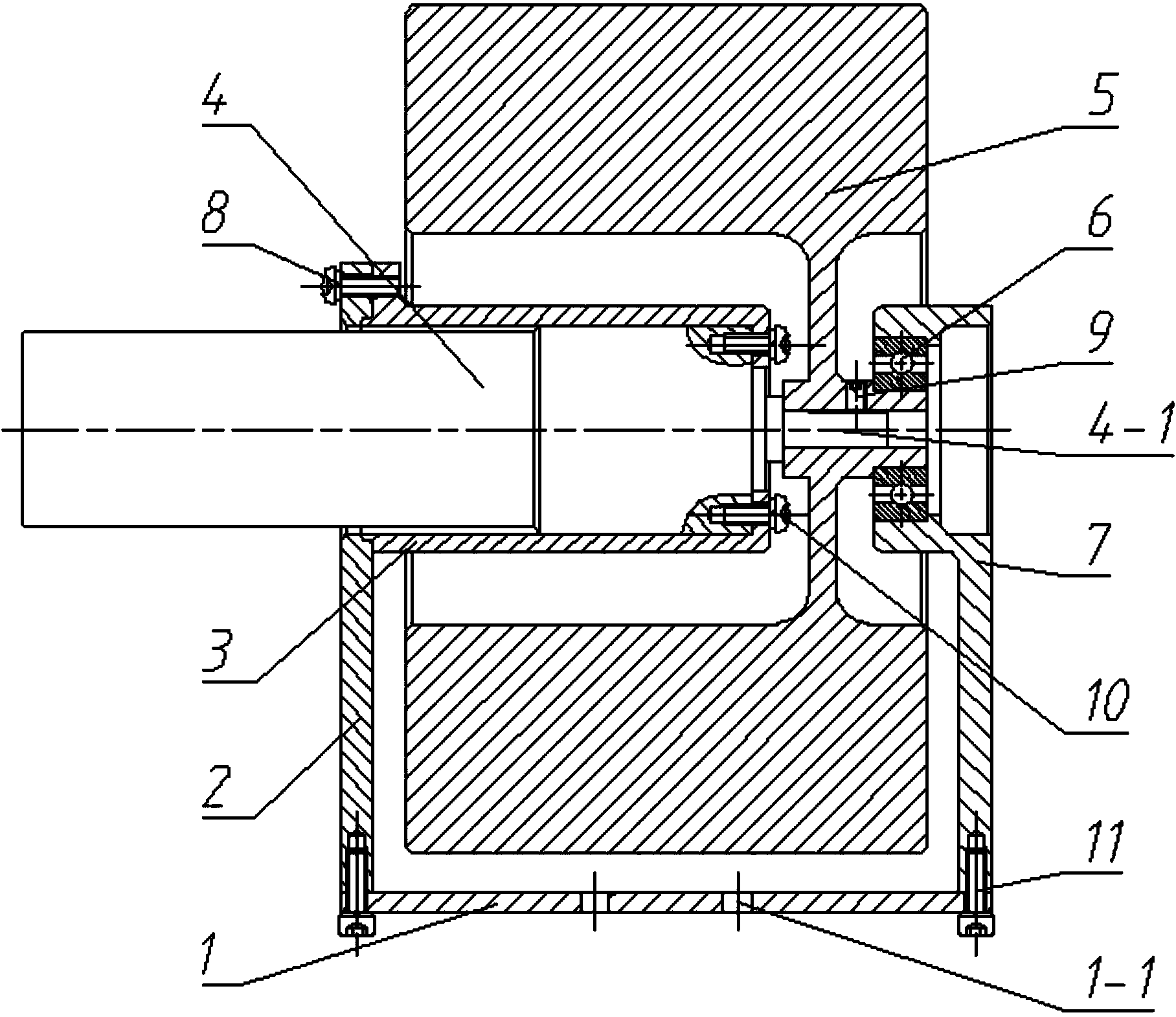
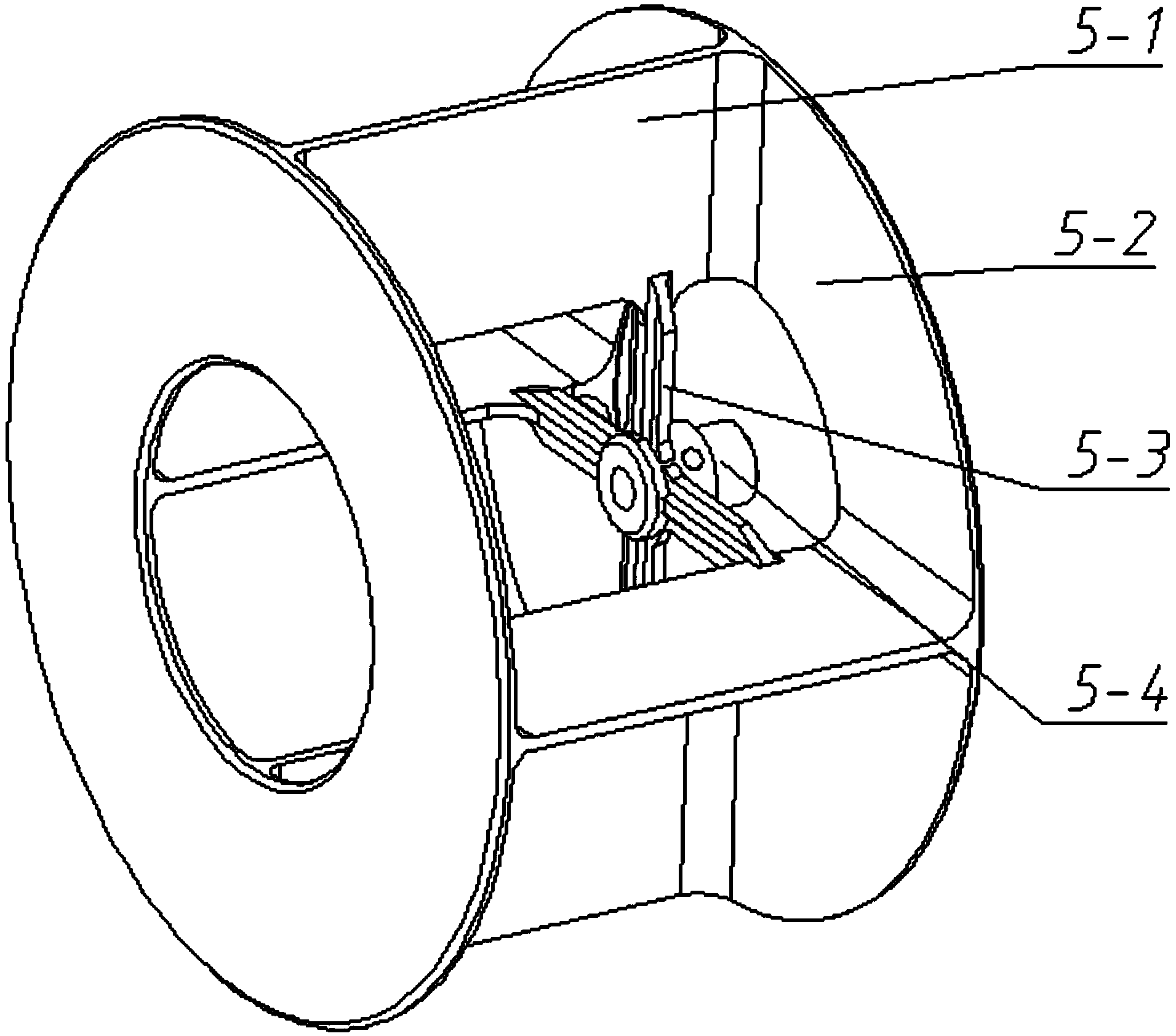
[0015] like figure 1 It is a schematic diagram of the structure of the present invention, figure 2 It is a schematic diagram of the flywheel structure of the present invention, and the composite reaction flywheel includes a fixed plate 1, a support plate 2, a motor fixing seat 3, a reduction motor 4, a flywheel 5, a bearing 6, a bearing support 7, a screw a8, and a set screw 9 , screw b10, screw c11, wherein the support plate 2 and the bearing support 7 are fixed on the fixing plate 1 through the screw c11; The plate 2 is fixed, and the reduction motor 4 and the three motors are fixed by screws b10; the flywheel 5 includes a blade 5-1, a flange 5-2, a spoke plate 5-3 and a hollow flywheel shaft 5-4, of which four The two blades 5-1 are evenly arranged along the circumference, the two ends of the four blades 5-1 are respectively connected with the flange 5-2, the spo...


PUM


Abstract

The invention relates to a combined type counteractive fly wheel. The combined type counteractive fly wheel comprises a fixing plate, a supporting plate, a motor fixing base, a speed reducing motor, a fly wheel body, a bearing and a bearing support. The fixing plate is respectively and fixedly connected to the supporting plate and the bearing support. The speed reducing motor is fixed to the supporting plate through the motor fixing base. The speed reducing motor drives the fly wheel body to rotate, and the other end of the fly wheel body is fixed to the bearing support through the bearing. The fly wheel body comprises a plurality of blades, two flanges, wheel disks and a hollow type fly wheel rotating shaft, wherein the blades are evenly distributed along the circumference, the two ends of each blade are respectively connected with one flange, the wheel disks are fixedly connected with the hollow type fly wheel rotating shaft, each blade is connected through one wheel disk, and the speed reducing motor drives the blades to generate inertia restoring torque and pneumatic restoring torque through the fly wheel rotating shaft and the wheel disks respectively. According to the combined type counteractive fly wheel, the fly wheel speed saturation phenomenon can be effectively delayed, and the combined type counteractive fly wheel has high controllability.

Description

technical field [0001] The invention relates to a flywheel, which belongs to the field of attitude-controlled reaction flywheels, in particular to a composite reaction flywheel. Background technique [0002] As a key component of attitude adjustment, the reaction flywheel has been widely used in the fields of satellites, one-wheeled robots and other aircraft and robots. The reaction torque generated by the conventional reaction flywheel is proportional to its rotational angular acceleration and has nothing to do with the rotation speed of the reaction flywheel. The speed saturation phenomenon of the reaction flywheel is easy to occur during the working process, resulting in the failure of the reaction flywheel. Contents of the invention [0003] In order to overcome the above-mentioned deficiencies of conventional reaction flywheels, the invention provides a composite reaction flywheel, and the specific technical scheme is as follows: [0004] The object of the present in...

Claims


Application Information

Patent Timeline
Patent Type & Authority Applications(China)
IPC IPC(8): H02K7/02
CPCY02E60/16
Inventor 阮晓钢陈志刚王旭朱晓庆魏若岩张晓平庞涛肖尧
Owner BEIJING UNIV OF TECH
Why Eureka
Try Eureka