
Power line communication equipment and power line communication method

A technology of power line communication and equipment, which is applied in the direction of distribution line transmission system, etc., can solve the problems of increased conduction interference, device cost, equipment size, circuit design difficulty, equipment management and configuration complexity, etc., to reduce conduction interference and equipment Power consumption, the effect of lowering barriers to entry

Active Publication Date: 2014-07-02
CHINA TELECOM CORP LTD
View PDF10 Cites 3 Cited by
  • Summary
  • Abstract
  • Description
  • Claims
  • Application Information

AI Technical Summary

Problems solved by technology

[0008] A technical problem to be solved by the embodiments of the present invention is to solve the problem of the integration of the information interface and the power supply interface in the traditional power line communication equipment, which increases the conduction interference
[0009] Another technical problem to be solved by the embodiments of the present invention is to solve the problem that the strong power supply in traditional power line communication equipment needs to implement a transformer in the equipment, which leads to increased device cost, equipment volume, and difficulty in circuit design
[0010] Another technical problem to be solved by the embodiment of the present invention is to solve the problem of complex device management and configuration in traditional power line communication devices for users who do not understand the local network management method

Method used


Image

  • Power line communication equipment and power line communication method
  • Power line communication equipment and power line communication method
  • Power line communication equipment and power line communication method

Examples


Embodiment Construction

[0030] The following will clearly and completely describe the technical solutions in the embodiments of the present invention with reference to the accompanying drawings in the embodiments of the present invention. Obviously, the described embodiments are only some, not all, embodiments of the present invention. The following description of at least one exemplary embodiment is merely illustrative in nature and in no way taken as limiting the invention, its application or uses. Based on the embodiments of the present invention, all other embodiments obtained by persons of ordinary skill in the art without creative efforts fall within the protection scope of the present invention.

[0031] The relative arrangements of components and steps, numerical expressions and numerical values ​​set forth in these embodiments do not limit the scope of the present invention unless specifically stated otherwise.

[0032] At the same time, it should be understood that, for the convenience of d...


PUM


Abstract

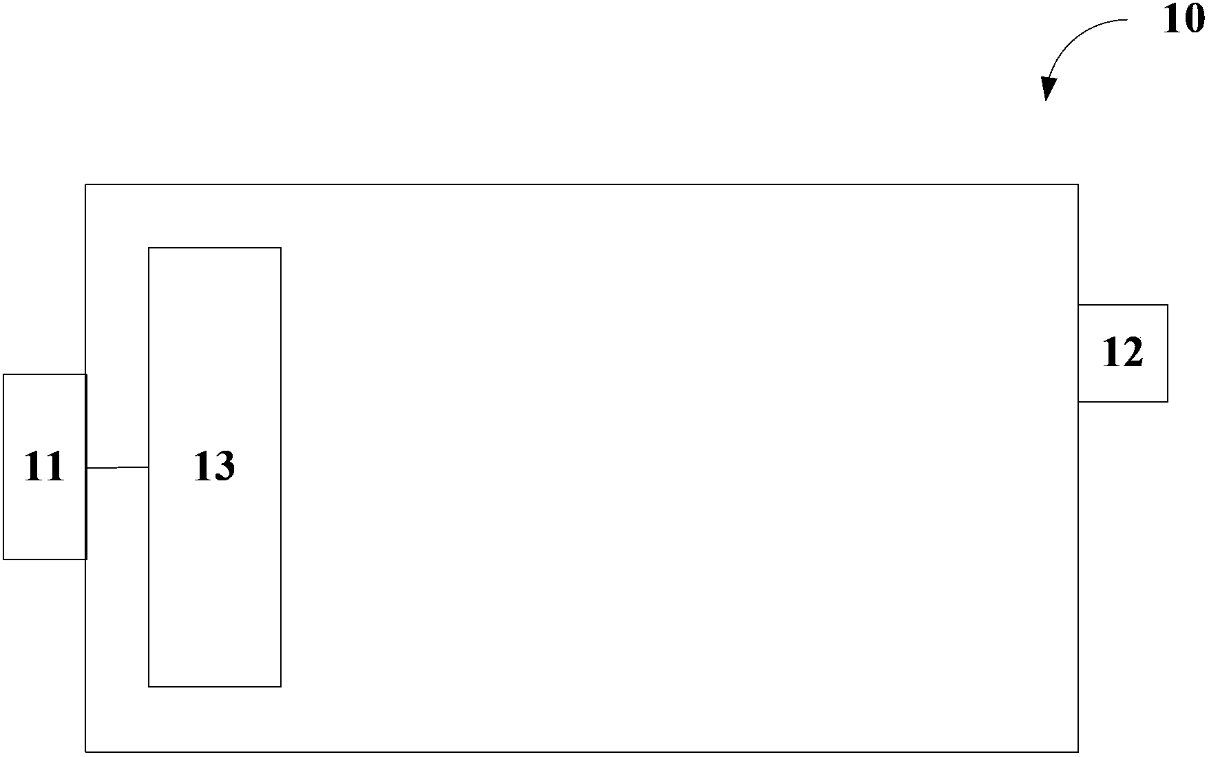
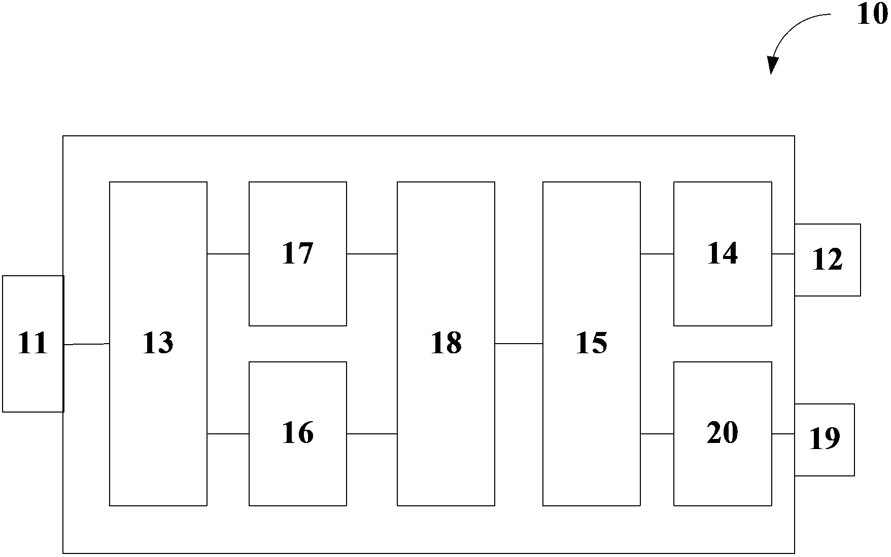
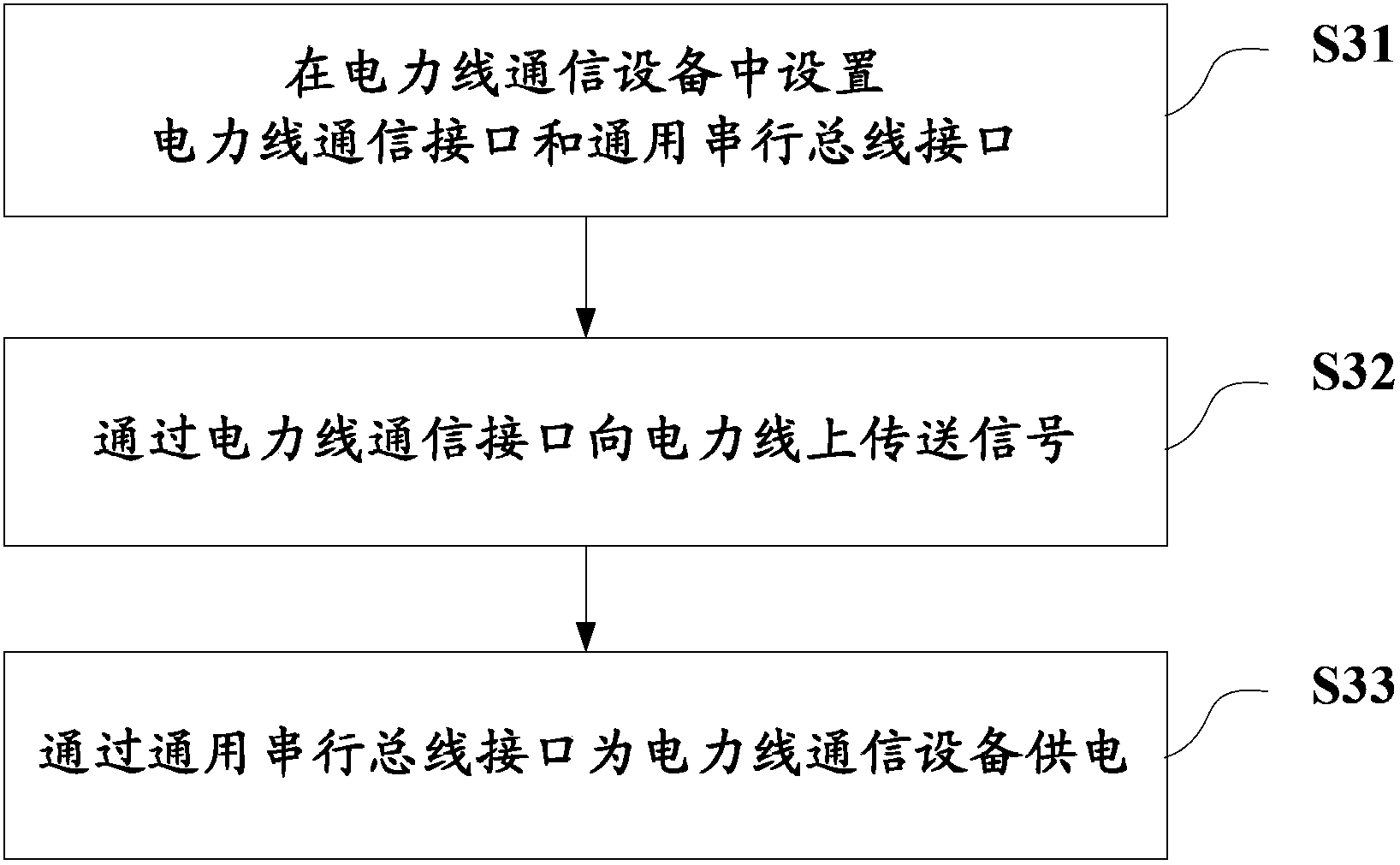
The invention discloses a piece of power line communication equipment and a power line communication method, and relates to the field of terminals. The power line communication equipment comprises a power line communication interface, a universal serial bus interface and a signal coupling unit. The power line communication interface is connected with the signal coupling unit and is used for transmitting a signal to the signal coupling unit. The signal coupling unit is used for coupling or decoupling the signal. The universal serial bus interface is used for supplying power to the power line communication equipment. According to the invention, weak power supply is carried out based on the USB interface. On one hand, compared with strong power supply, power consumption of the equipment can be reduced, fewer transformers are required, the device cost is reduced, the product size is reduced, the difficulty in wiring design is reduced, the access threshold for equipment design and production is lowered, and the rise of the power line communication market is benefited. On the other hand, power supply interfaces are separated and an information interface is independently arranged, conductive interference on the power line communication interface is reduced, and the equipment can easily meet the electromagnetic compatibility certification requirements.

Description

technical field [0001] The present invention relates to the field of terminals, in particular to a power line communication device and method. Background technique [0002] G.hn technology is an indoor networking communication technology that can be transmitted on three media: telephone line, coaxial cable, and power line. It is also called "wired networking technology based on a common medium". [0003] G.hn power line communication equipment provides a convenient and fast home networking solution for services such as iTV and FTTH (Fiber to the Home, fiber to the home). iTV business uses broadband network as channel, TV as display terminal, integrates Internet, multimedia and communication technologies, and provides users with interactive video services such as on-demand and live broadcast. It is a brand-new broadband value-added service. [0004] However, traditional power line communication usually uses two power line adapters to supply power through the indoor power int...

Claims


Application Information

Patent Timeline
Patent Type & Authority Applications(China)
IPC IPC(8): H04B3/54
Inventor 张荣王作强卢燕青陆立何峣杨敏维贾聿庸朱先飞黎艳郭茂文郭建昌
Owner CHINA TELECOM CORP LTD
Learn More