IQ calibration and compensation method and device

A compensation method and compensation module technology, applied in the field of communication, can solve problems such as long time, high-frequency symbol rate, and large amount of data

Active Publication Date: 2014-07-02
SANECHIPS TECH CO LTD
View PDF5 Cites 13 Cited by
  • Summary
  • Abstract
  • Description
  • Claims
  • Application Information

AI Technical Summary

Problems solved by technology

However, there is a high intermediate frequency symbol rate in microwave systems or high-speed transmission systems, the traditional IQ calibration blind estimation algorithm counts more data, takes longer, and the calculation process is slow and complicated

Method used


Image

  • IQ calibration and compensation method and device
  • IQ calibration and compensation method and device
  • IQ calibration and compensation method and device

Examples


Embodiment Construction

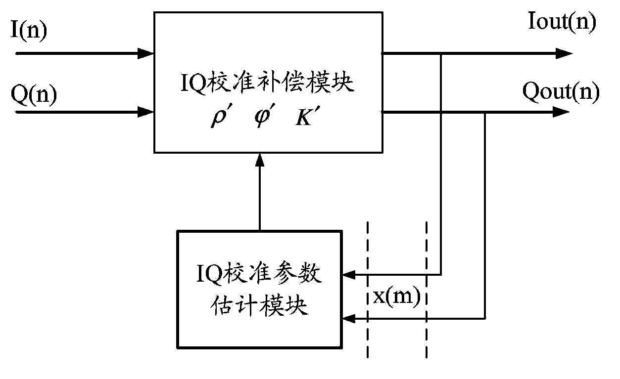
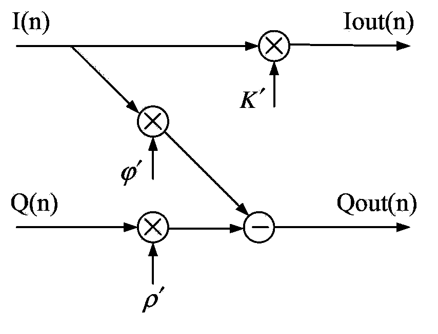
[0061] In order to solve the problems of long statistical time and slow and complicated calculation process of the IQ calibration blind estimation algorithm in the IDU of the receiving end of the existing microwave system, it is ensured that the calculation is simple, the calculation time is small and the estimation is accurate during IQ calibration. can be used as figure 1 The feedback structure shown. figure 1 Among them, the output of the IQ calibration compensation module is connected to the input of the IQ calibration parameter estimation module, and the output of the IQ calibration parameter estimation module is connected to the input of the IQ calibration compensation module, so that the IQ calibration compensation module and the IQ calibration parameter estimation module form a feedback structure. In actual application, the IQ calibration compensation module receives the input IQ signal, and based on the compensation parameters (amplitude gain of the Q path, phase esti...


PUM


Abstract

Disclosed are an IQ calibration compensation method and apparatus. In an IQ signal output by an IQ calibration compensation module, an accumulated value of an absolute value of an I path and an accumulated value of an absolute value of a Q path are filtered separately to obtain a magnitude gain of the Q path; an accumulated value of a product of the I path and the Q path and an accumulated value of a square of the I path are filtered separately to obtain a phase estimation of the Q path and a magnitude gain of the I path; and the IQ calibration compensation module performs IQ calibration compensation that does not comprise a matrix iteration process based on the magnitude gain and the phase estimation of the Q path and the magnitude gain of the I path, so as to output an IQ signal that has been compensated for. The present invention performs the filtering processing in the process of generating a compensation parameter, so that the present invention no longer needs to perform a matrix iteration process in an IQ calibration compensation method in the prior art, influence of non-uniform distribution of sampled data is reduced, a data statistical amount is increased, and the accuracy and stability of IQ calibration are ensured.

Description

technical field [0001] The invention relates to the communication field, in particular to an in-phase and quadrature (IQ) calibration compensation method and device. Background technique [0002] In a microwave system, the signals of different bandwidths in the indoor unit (IDU) part of the transmitting end pass through the digital intermediate frequency and the analog intermediate frequency and then are sent out through the outdoor unit (ODU) and the antenna, while the receiving end passes through the antenna and the outdoor unit (ODU) Receive the radio frequency signal, convert the received radio frequency signal into an intermediate frequency signal, and then perform corresponding demodulation after passing through the analog intermediate frequency and digital intermediate frequency. In the process of simulating the intermediate frequency, there is a zero-IF processing process, that is, the intermediate frequency carrier signal is down-converted through the analog local o...

Claims


Application Information

Patent Timeline
Patent Type & Authority Applications(China)
IPC IPC(8): H04L27/38
CPCH04L27/36H04L27/364
Inventor 张国智
Owner SANECHIPS TECH CO LTD
Why Eureka
Try Eureka