3D positioning method and device based on PTZ surveillance camera

A monitoring camera and video camera technology, applied in image communication, color TV parts, TV system parts, etc., can solve time-consuming and labor-intensive problems, and achieve the effect of simplifying mathematical operations, fast acquisition, and direct positioning

Active Publication Date: 2014-07-02
武汉众智数字技术有限公司
View PDF5 Cites 39 Cited by
  • Summary
  • Abstract
  • Description
  • Claims
  • Application Information

AI Technical Summary

Problems solved by technology

[0004] In view of the above problems, the object of the present invention is to provide a PTZ-based surveillance camera and its 3D positioning method, aiming to solve the problem that

Method used


Image

  • 3D positioning method and device based on PTZ surveillance camera
  • 3D positioning method and device based on PTZ surveillance camera
  • 3D positioning method and device based on PTZ surveillance camera

Examples


Embodiment 1

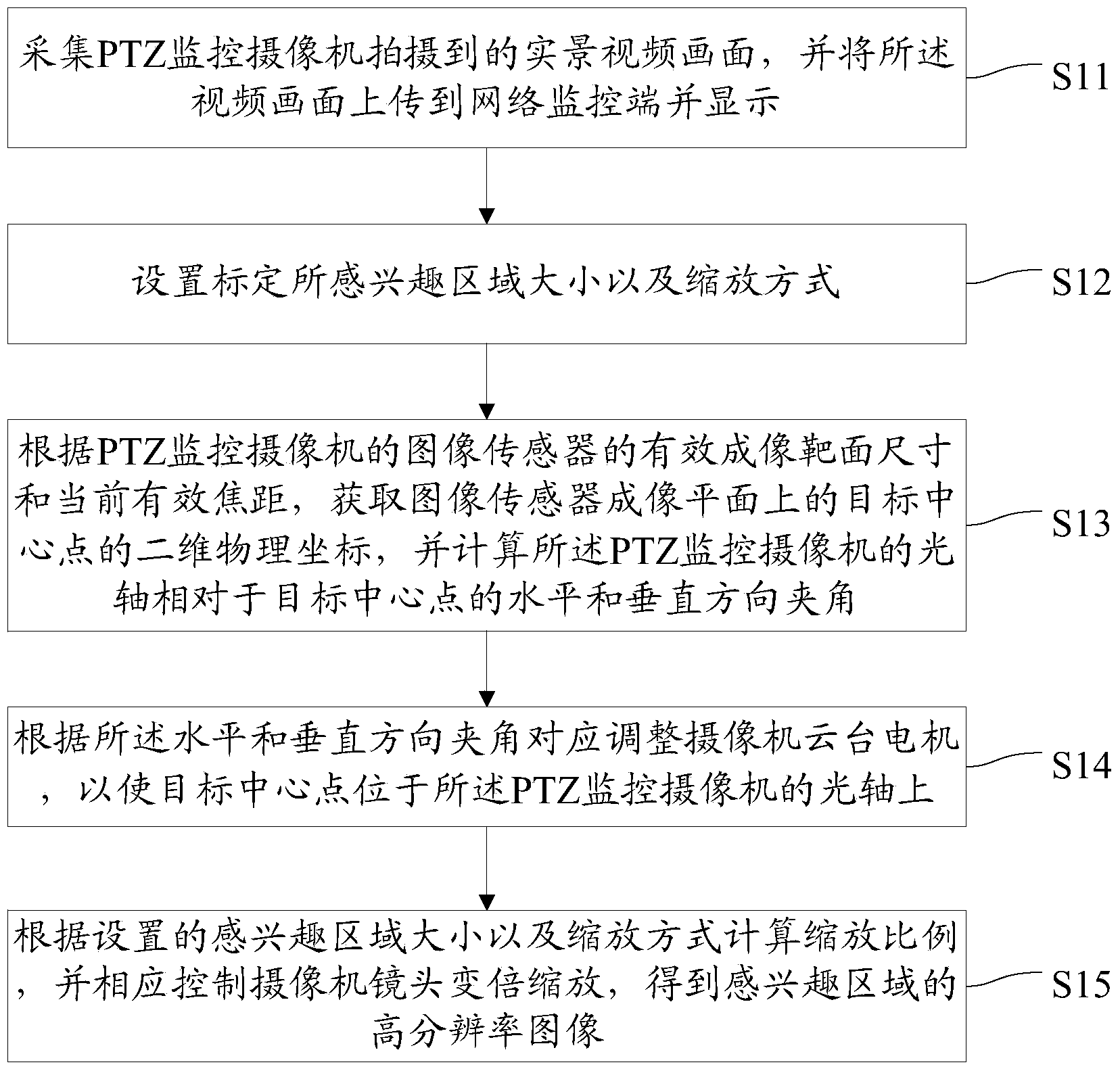
[0027] figure 1 The flow of the 3D positioning method for a PTZ surveillance camera provided by the embodiment of the present invention is shown, and only the parts related to the embodiment of the present invention are shown for convenience of description.

[0028] The 3D positioning method based on the PTZ monitoring camera provided by the present embodiment includes the following steps:

[0029] Step S11, collecting the real scene video picture taken by the PTZ surveillance camera, uploading the video picture to the network monitoring terminal and displaying it.

[0030] The PTZ surveillance camera is usually a dome camera with a built-in camera pan / tilt. By adjusting the camera pan / tilt, the panning and tilting of the camera lens can be adjusted. The PTZ monitoring camera is a network camera, which is connected to the background network monitoring terminal through the network, and the video images captured by each camera can be displayed in real time on the network monito...

Embodiment 2

[0056] Figure 5 The structure of the 3D positioning device based on the PTZ surveillance camera provided by the embodiment of the present invention is shown, and only the parts related to the embodiment of the present invention are shown for convenience of description.

[0057] The 3D positioning device based on the PTZ monitoring camera provided in this embodiment includes:

[0058] Video acquisition output module 51, is used for gathering the real-scene video picture that PTZ monitoring camera shoots, and described video picture is uploaded to network monitoring terminal and shows;

[0059] The target locking setting module 52 is used to set the size of the region of interest for calibration and the zoom mode;

[0060] 3D conversion calculation module 53, for obtaining the two-dimensional physical coordinates of the target center point on the imaging plane of the image sensor according to the effective imaging target size and the current effective focal length of the image...


PUM


Abstract

The invention belongs to the technical field of security and protection monitoring and provides a 3D positioning method based on a PTZ surveillance camera. The method comprises the steps of acquiring a live-action video picture shot by the PTZ surveillance camera, setting the size of an interested area and the scaling method; acquiring the two-dimensional physical coordinates of a target center point on an imaging plane of an image sensor and the horizontal included angle and vertical included angle, relative to the target center point, of the optical axis of the PTZ surveillance camera, adjusting a camera PTZ motor correspondingly according to the horizontal included angle and vertical included angle, and calculating scaling according to the set size of the interested area and scaling method and controlling a lens of the camera to zoom correspondingly to obtain a high-resolution image of the interested area. According to the method, the 3D coordinate fast conversion algorithm is adopted, direction positioning of the interested area is achieved, and the high-resolution image of the interested area can be acquired accurately and quickly.

Description

technical field [0001] The invention belongs to the field of security monitoring, and in particular relates to a 3D positioning method and device based on a PTZ monitoring camera. Background technique [0002] PTZ camera is a surveillance camera. In security surveillance applications, PTZ is the abbreviation of Pan / Tilt / Zoom. Because of its variable viewing angle and variable focus capabilities, PTZ cameras can change the shooting angle, coverage and definition at any time. Compared with ordinary cameras, they can obtain better monitoring effects. Therefore, PTZ cameras have been more and more widely used in the current surveillance market. [0003] The rotation and zoom characteristics of the PTZ camera during motion allow the region of interest to "move across" the screen as the camera pans and tilts. At low tilt angles, the region of interest appears to move horizontally across the screen. However, at higher tilt angles (greater than 45 degrees), the ROI appears to mov...

Claims


Application Information

Patent Timeline
IPC IPC(8): H04N7/18H04N5/232
Inventor 曹木莲罗巍
Owner 武汉众智数字技术有限公司
Why Eureka
Try Eureka