
Power conversion device

A technology for power conversion devices and mounting substrates, which is applied to circuits, electrical components, electrical solid-state devices, etc., can solve the problems of reduced cooling efficiency, increased thermal resistance, and large-scale power conversion devices, and achieves the effect of miniaturization.

Inactive Publication Date: 2014-07-02
FUJI ELECTRIC CO LTD
View PDF5 Cites 1 Cited by
  • Summary
  • Abstract
  • Description
  • Claims
  • Application Information

AI Technical Summary

Problems solved by technology

Liquid sealants and rubber seals generally have low thermal conductivity, and if they are placed in the heat radiation cooling path, there are still unsolved problems such as increased thermal resistance and reduced cooling efficiency.
In order to solve this unsolved problem, it is also necessary to use natural convection from the frame body and frame body cover to dissipate heat that cannot be completely eliminated from the substrate and mounting parts. The surface area of ​​the frame body and frame body cover increases, so the frame body, frame body cover The outer shape of the case cover becomes larger, resulting in an increase in the size of the power conversion device

Method used


Image

  • Power conversion device
  • Power conversion device
  • Power conversion device

Examples


Embodiment Construction

[0034] Embodiments of the present invention will be described below with reference to the drawings.

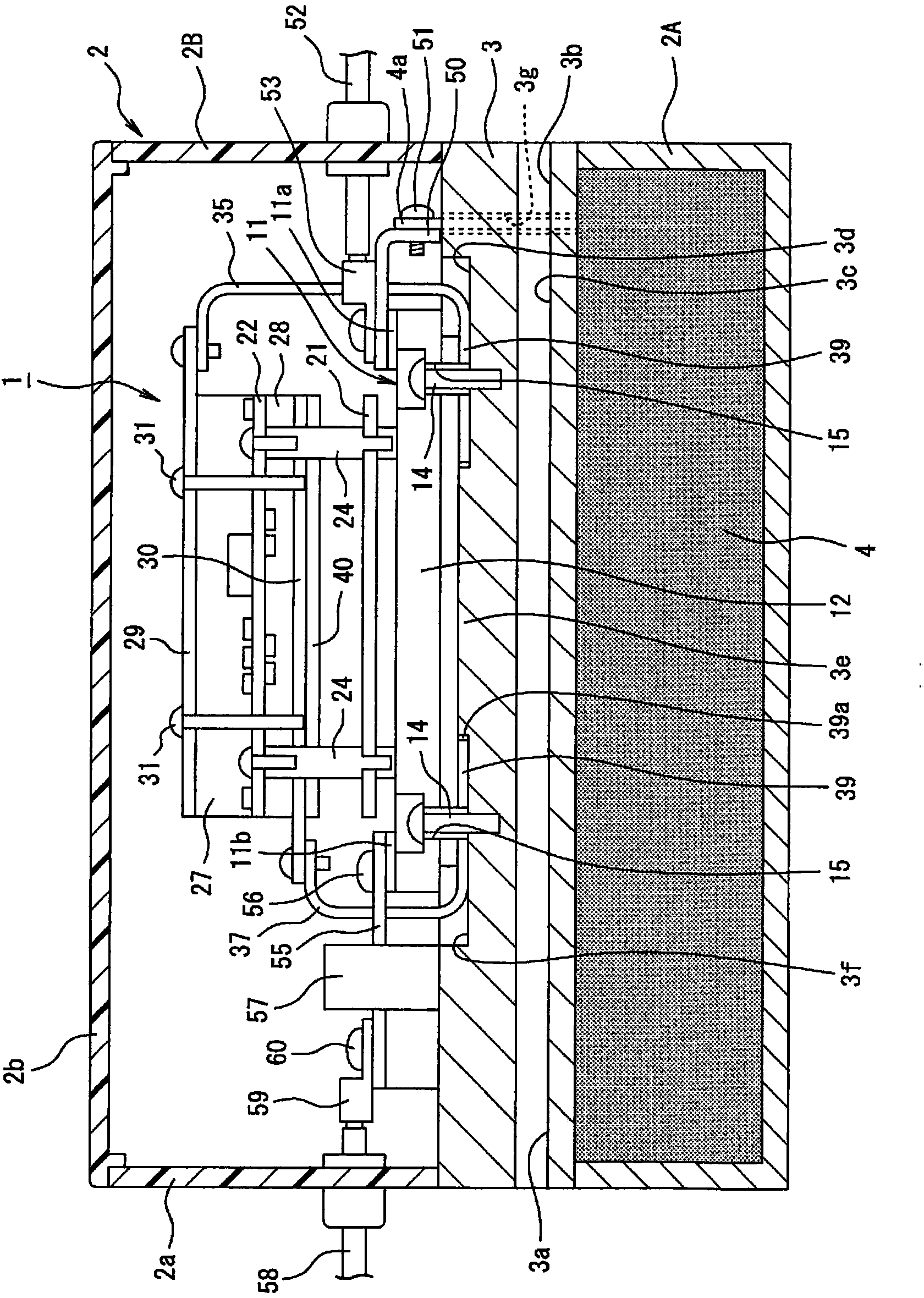
[0035] figure 1 It is a sectional view showing the overall structure of the power conversion device of the present invention.

[0036] In the drawings, reference numeral 1 denotes a power conversion device, and the power conversion device 1 is accommodated in a casing 2 . The frame body 2 is a frame body molded from a synthetic resin material, and is composed of a lower frame body 2A and an upper frame body 2B which are vertically divided through a cooling body 3 having a water jacket structure.

[0037] The lower housing 2A is composed of a bottomed square cylinder. The open upper portion of the lower housing 2A is covered with a cooling body 3 , and a smoothing film capacitor 4 is housed inside the lower housing 2A.

[0038] The upper frame 2B includes a square cylinder 2a with open upper and lower ends and a cover 2b for closing the upper end of the square cylinder 2a. ...


PUM


Abstract

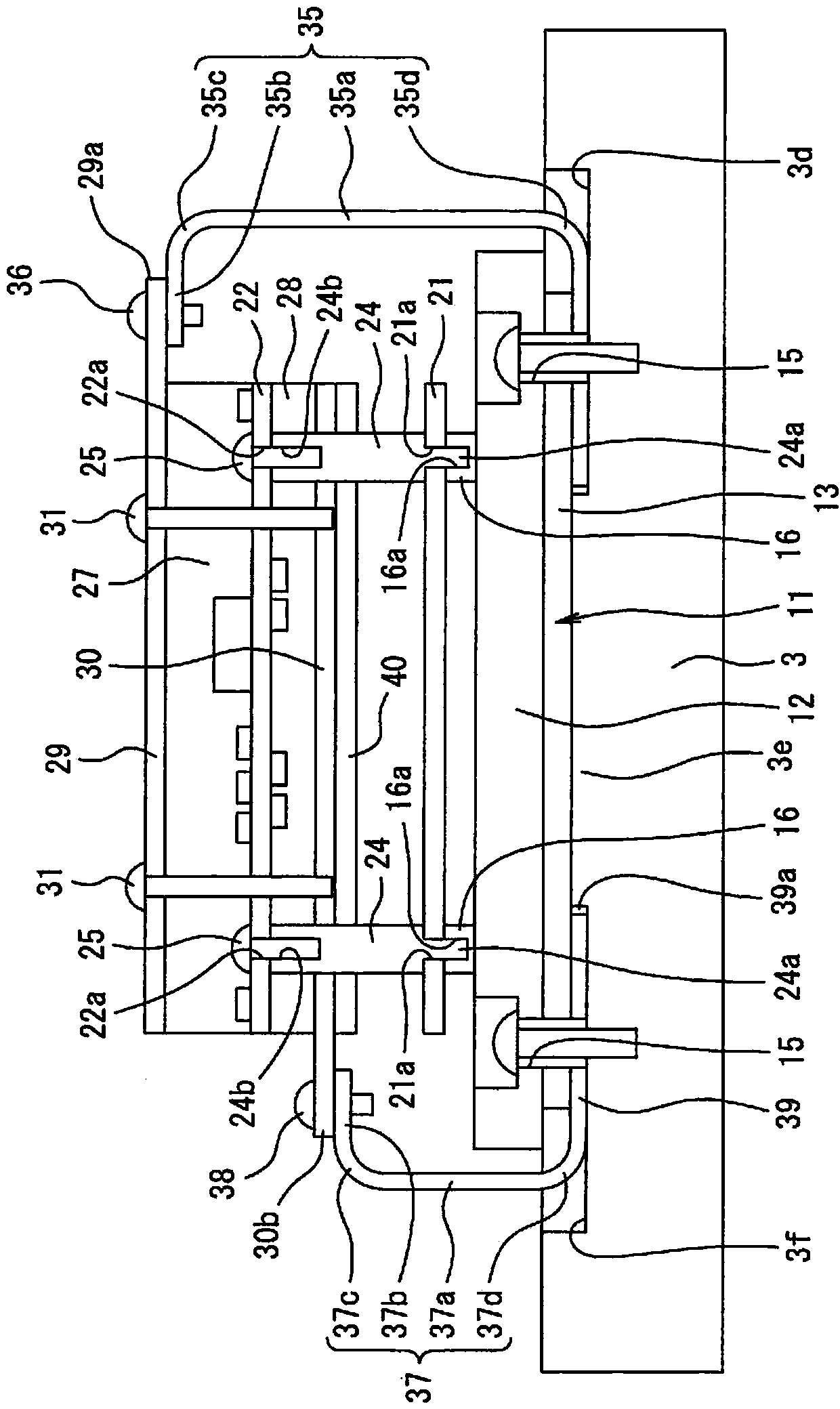
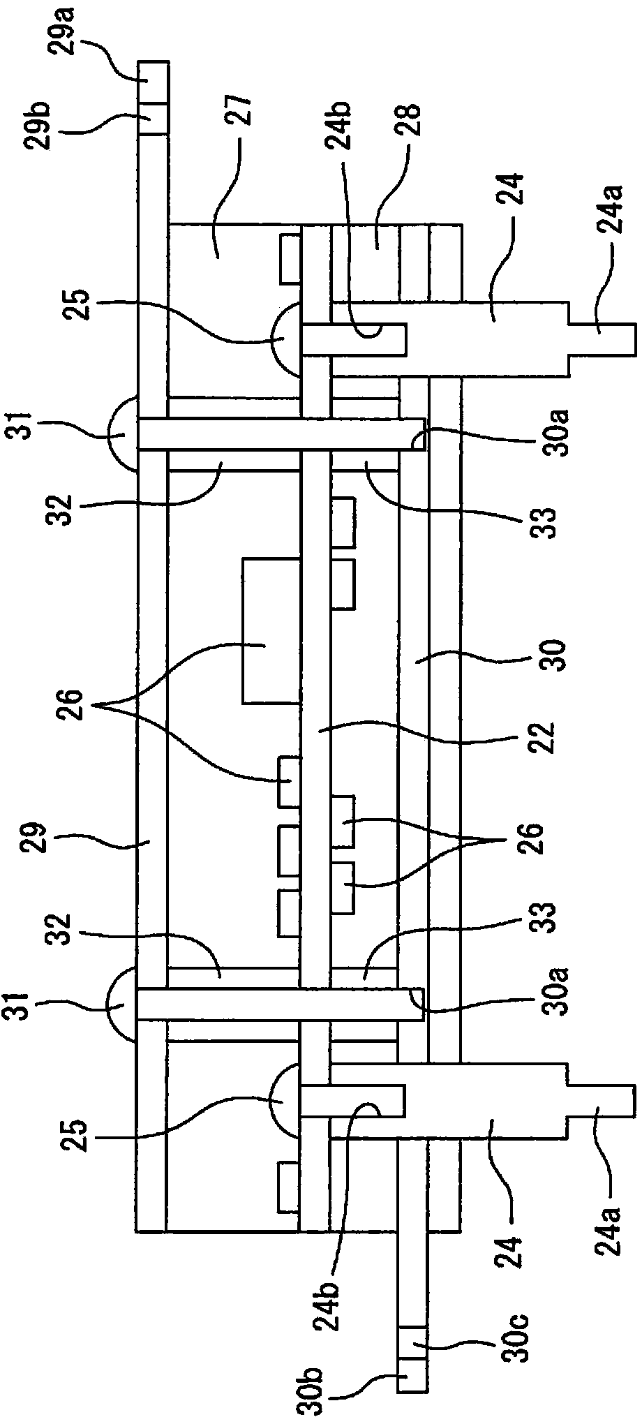
Provided is a power conversion device which is capable of miniaturization and of efficiently radiating, into a cooling body, heat from a heat-generating circuit component mounted on a substrate. This power conversion device (1) is provided with a semiconductor power module (11) with one surface bonded to the cooling body (3), a mounting substrate (22) on which circuit components are mounted that include a heat-generating circuit component which drives the semiconductor power module (11), and heat conduction paths (35, 37) which transfer the heat from the mounting substrate into the cooling body (3). Heat conducting members (27, 28) are arranged on both the front and back surfaces of the mounting substrate (22).

Description

technical field [0001] The present invention relates to a power conversion device for supporting a mounting substrate on which a circuit component including a heating circuit component for driving the semiconductor switching element is mounted on a semiconductor power module incorporating a semiconductor switching element for power conversion. Background technique [0002] As such a power conversion device, the power conversion device described in Patent Document 1 is known. In this power conversion device, a water cooling jacket is arranged in a frame, and a semiconductor power module including an IGBT as a semiconductor switching element for power conversion is built in and cooled by arranging a semiconductor power module on the water cooling jacket. In addition, the control circuit board and the driving circuit board are arranged at a predetermined distance on the side opposite to the water cooling jacket of the semiconductor power module in the frame, and the heat genera...

Claims


Application Information

Patent Timeline
Patent Type & Authority Applications(China)
IPC IPC(8): H01L23/36H01L23/34H01L25/07H01L25/18
CPCH01L23/36H01L2924/0002H01L23/4006H01L25/162H01L23/473H05K7/20927H01L2924/00
Inventor 田中泰仁柴田美里
Owner FUJI ELECTRIC CO LTD
Learn More