
Electric control breathing machine or anesthesia machine active exhalation valve based automatic calibration method

A ventilator and anesthesia machine technology, which is applied in the field of automatic calibration based on electric electronically controlled ventilator or active exhalation valve of anesthesia machine, which can solve the problem of high maintenance cost, failure of exhalation valve calibration, poor product reliability and stability and other problems, to achieve accurate measurement results, reduce maintenance costs, and good stability

Inactive Publication Date: 2014-07-09
BEIJING AEONMED
View PDF5 Cites 5 Cited by
  • Summary
  • Abstract
  • Description
  • Claims
  • Application Information

AI Technical Summary

Problems solved by technology

However, there is no accurate and convenient method for detecting the correspondence between the control voltage of the exhalation valve and the final PEEP value in the prior art
[0004] Based on the above description, there is an urgent need for a method for measuring the correspondence between the control voltage of the exhalation valve and the final PEEP value, so as to solve the problem that the exhalation valve cannot be automatically calibrated by the ventilator or anesthesia machine in the prior art. Must rely on third-party testing equipment to calibrate it, resulting in high maintenance costs and poor product reliability and stability

Method used


Image

  • Electric control breathing machine or anesthesia machine active exhalation valve based automatic calibration method
  • Electric control breathing machine or anesthesia machine active exhalation valve based automatic calibration method

Examples


Embodiment Construction

[0032] The technical solutions of the present invention will be further described below through specific embodiments.

[0033] The automatic verification method of the active exhalation valve of the present invention is mainly applied to electric and electronically controlled ventilators, anesthesia machines and other equipment that need to verify the exhalation valve.

[0034] The electric electronically controlled ventilator is mainly composed of a motor with a turbine to control the flow rate, an inhalation valve, a pipe, and an exhalation valve. The specific connection structure is: the rear end of the motor with a turbine is connected to the inhalation valve, and the inhalation The rear end of the valve is connected with an air intake pipeline, the air intake pipeline leads to the lungs, the other end of the lungs communicates with the air outlet pipeline, and the other end of the air outlet pipeline is connected with an exhalation valve.

[0035] Moreover, the rotational...


PUM


Abstract

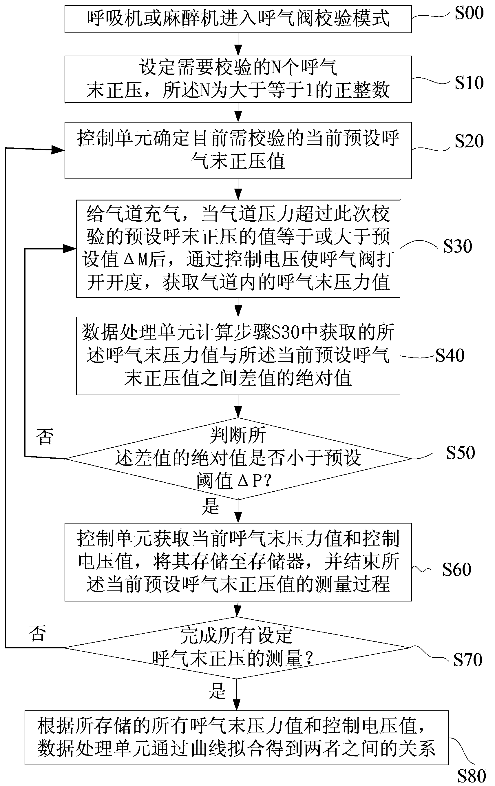
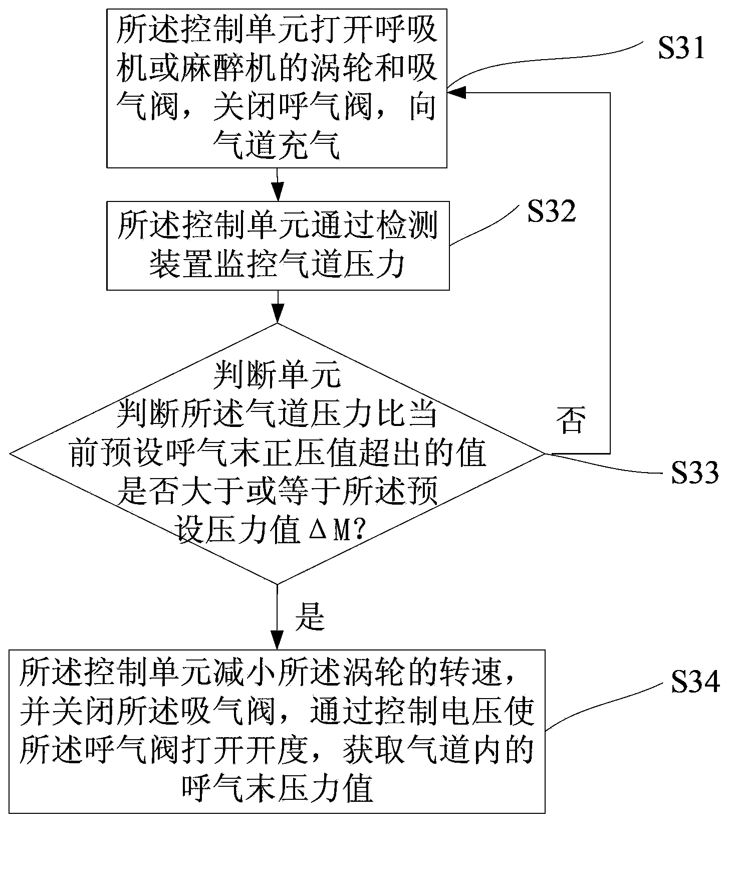
The invention discloses an electric control breathing machine or anesthesia machine active exhalation valve based automatic calibration method. The electric control breathing machine or anesthesia machine active exhalation valve based automatic calibration method comprises step S00, entering into an exhalation valve calibration mode; step S10, setting N positive end-expiratory pressure values; step S20, determining a preset positive end-expiratory pressure value; step S30, performing inflation on an air channel and obtaining the positive end-expiratory pressure in the air channel when the pressure of the air channel exceeds the preset positive end-expiratory pressure value to be calibrated and is not less than a preset value Delta M; step S40, calculating an absolute value of a difference value between an end-expiratory pressure value and the current preset positive end-expiratory pressure value; step S50, judging whether the absolute value of the difference value is smaller than a preset threshold value Delta P or not, executing step S60 if yes and executing the step S30 otherwise; step S60, storing the end-expiratory pressure value and a control voltage value; step S70, judging whether measurement of the positive end-expiratory pressure values is achieved or not, executing step S80 if yes and executing the step S20 otherwise; step S80, obtaining the relation between end-expiratory pressure values and control pressure values through curve fitting.

Description

technical field [0001] The present invention relates to the field of ventilator or anesthesia machine, more specifically, relates to an automatic calibration method based on the active exhalation valve of the electric electronically controlled ventilator or anesthesia machine. Background technique [0002] In order to ensure that the alveoli do not collapse when the patient is using a ventilator or anesthesia machine, it is necessary to maintain a certain airway pressure at the end of expiration. PEEP) value remains the same. For turbo ventilators, most of them need to maintain two pressure levels. Generally, it is high pressure when inhaling, and the pressure can be set according to needs. It is low pressure when exhaling, and generally maintains the set PEEP value. Since the actual PEEP in the airway is mainly realized and guaranteed by the active exhalation valve, the precise calibration of the exhalation valve is very critical, and the conventional calibration method ha...

Claims


Application Information

Patent Timeline
Patent Type & Authority Applications(China)
IPC IPC(8): A61M16/20G01M13/00
Inventor 金文贤
Owner BEIJING AEONMED
Learn More