Unlock instant, AI-driven research and patent intelligence for your innovation.

Preparation method, equipment and product of powder sintered porous filter element

A filter element and powder technology, which is applied in the field of preparation of powder sintered porous filter elements, can solve the problems of affecting the use of filter elements, uneven particle size of particles, and inconsistent filtration performance and filtration accuracy.

Active Publication Date: 2016-08-17
CHENGDU INTERMENT TECH
View PDF12 Cites 0 Cited by
  • Summary
  • Abstract
  • Description
  • Claims
  • Application Information

AI Technical Summary

Problems solved by technology

When the particle size in the powder raw material is uneven, the pore size difference of different parts on the powder sintered porous filter element will also be large. At this time, the filtration performance of different parts on the powder sintered porous filter element (mainly filter Accuracy) will be inconsistent, which will affect the use of filter elements
At present, in the face of the problem of uneven particle size in powder raw materials, the field often adopts methods such as strengthening raw material purchase restrictions or increasing particle screening, which has a certain impact on actual production

Method used


Image

  • Preparation method, equipment and product of powder sintered porous filter element
  • Preparation method, equipment and product of powder sintered porous filter element
  • Preparation method, equipment and product of powder sintered porous filter element

Examples


preparation example Construction

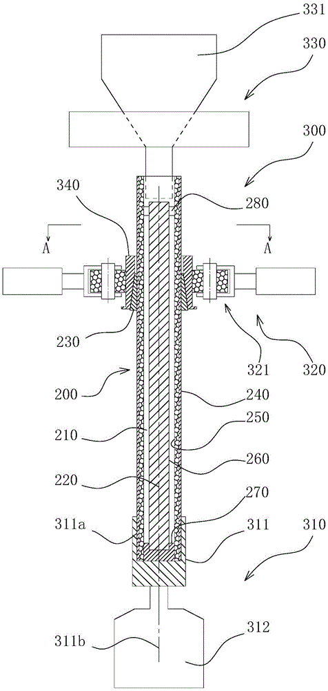
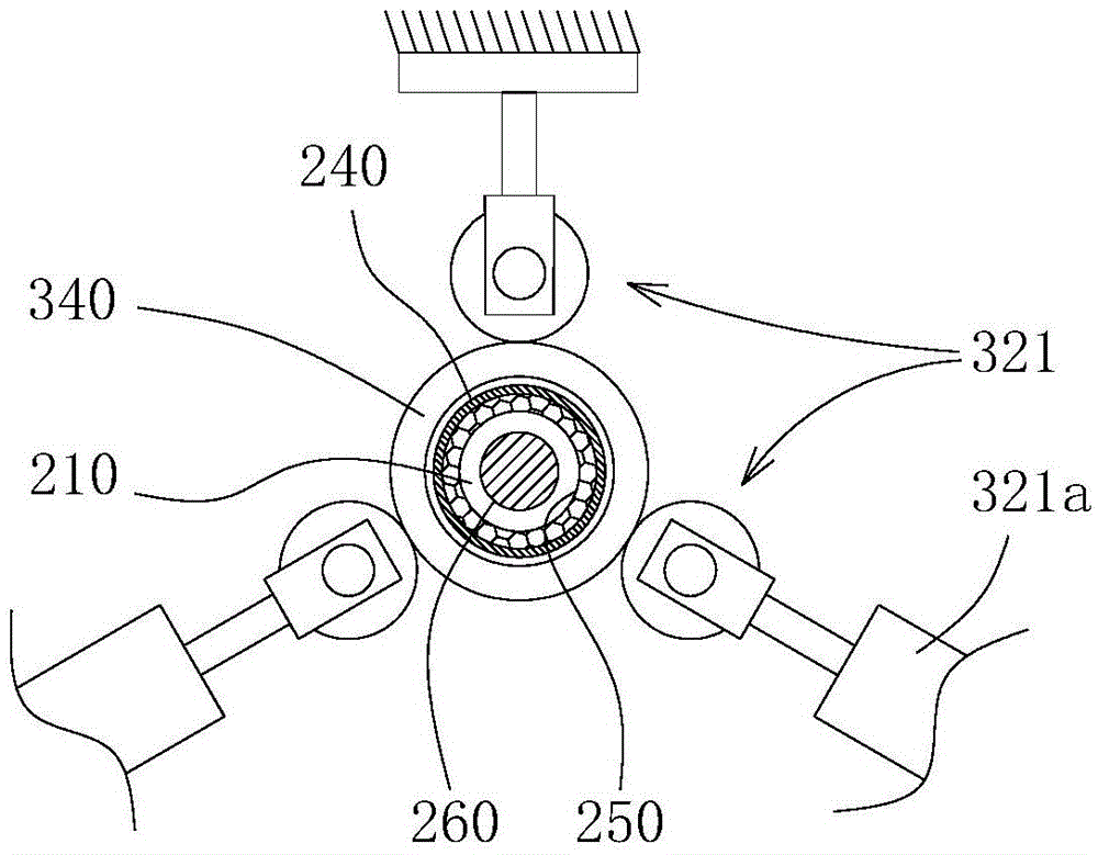
[0015] Such as figure 2 with 3 As shown, the method for preparing the powder sintered porous filter element includes the steps: a. Assemble an isostatic pressing mold 200 for manufacturing the intermediate tube blank of the filter element, and then install the isostatic pressing mold 200 to a Rotary injection device 300; b. Fill the mold cavity 210 with powder material through the rotary injection device 300 and drive the isostatic pressing mold 200 with the center axis 220 of the mold cavity 210 as the rotation axis and proceed at a certain speed When filling the mold cavity 210 with powder material, the speed of the isostatic pressing mold 200 is maintained at 30-80 rpm, and after the filling is completed, the speed of the isostatic pressing mold 200 is adjusted to 300-1000 R / min; c. The isostatic pressing mold 200 filled with powder raw materials is encapsulated and then put into the isostatic pressing molding machine for molding, and after molding, the intermediate tube of ...

Embodiment

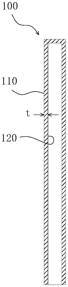
[0020] The design length of the powder sintered porous filter element 100 is 600 mm, and the design wall thickness t is 5 mm. First, the Cu element powder with a particle diameter of -250~+400 mesh and Ni element powder with a particle diameter of -200~+300 mesh are prepared according to the weight percentage of Cu in the powder sintered porous filter element, and the rest is The mixing ratio of Ni is mixed, granulated and dried to obtain a powder raw material. press figure 2 with 3 The powder raw material is filled into the mold cavity 210 in the manner shown and the isostatic pressing mold 200 is driven to rotate with the center axis 220 of the mold cavity 210 as the rotation axis, wherein when the powder raw material is filled into the mold cavity 210 The rotation speed of the isostatic pressing mold 200 is maintained at 50 rpm. After the filling is completed, the rotation speed of the isostatic pressing mold 200 is adjusted to 600 rpm, and the rotation speed is kept for 3 ...


PUM

PropertyMeasurementUnit
particle size (mesh)aaaaaaaaaa

Abstract

The invention discloses a powder sintering porous filter element production method, products obtained by the method, and equipment designed for implementing the method. The method is capable of utilizing the objective phenomenon that the particles in powder raw materials are uneven in size to increase the filter element of a powder sintering porous filter element. The method includes the steps of a, mounting an isostatic pressing forming die on a rotary filling device; b, using the rotary filling device to fill powder raw materials in a die cavity, and driving the isostatic pressing forming die to rotate at the speeder not lower than 50 rotation per minute by using the central axis of the die cavity as a rotation axis; c, encapsulating the isostatic pressing forming die filled with powder raw materials, and placing the encapsulated isostatic pressing forming die into an isostatic pressing forming machine for forming, taking a pressed and formed filter element intermediate tube blank out of the isostatic pressing forming die after forming; d, placing the tube blank in a sintering furnace, and sintering to allow the tube blank to convert into the powder sintering porous filter element.

Description

Technical field [0001] The invention relates to a method for preparing a powder sintered porous filter element, a product obtained by the method, and a device designed for implementing the method. Background technique [0002] The currently widely used powder sintered porous filter element is a tubular filter element with at least one end open. The outer side of the tube wall is the filter surface. During filtration, the filter medium (gas or liquid) is removed from the tube wall under pressure. The outer side faces the inner side of the tube wall and penetrates. The filtered medium that has been filtered and purified enters the lumen of the filter element and flows out from this lumen. Most of the trapped impurities are attached to the filter surface, and then applied on the filter element. The recoil medium flowing in the opposite direction to the above-mentioned filtering direction removes impurities from the filtering surface, so that the filtering element can be reused. The...

Claims


Application Information

Patent Timeline
Patent Type & Authority Patents(China)
IPC IPC(8): B22F3/16B22F3/04B22F5/12
Inventor 高麟汪涛曾伍祥
Owner CHENGDU INTERMENT TECH