
Casing-type underground pipeline leakage warning system and method based on fiber Bragg grating

A fiber grating and underground pipeline technology, applied in pipeline systems, mechanical equipment, gas/liquid distribution and storage, etc., can solve the problems of oil and gas pipelines that cannot be reused, single temperature monitoring, and replacement cannot be completed, so as to save cables and construction cost, no connection loss, light weight effect

Active Publication Date: 2016-05-04
QINGDAO HOUKE INFORMATION ENG
View PDF7 Cites 0 Cited by
  • Summary
  • Abstract
  • Description
  • Claims
  • Application Information

AI Technical Summary

Problems solved by technology

[0008] In the article "Fiber Bragg Grating Temperature and Strain Sensing System Applied in Oil and Gas Pipeline" published in "Laser Technology" Volume 31 Issue 1 in February 2007, a fiber grating temperature sensor is installed at the entrance and exit respectively. Install a pressure sensor in the station to obtain the variation of crude oil pressure and temperature in the oil and gas pipeline, so that according to different strain and temperature values, corresponding measures such as heating, pressurizing or decompression are taken in the station to ensure that the crude oil is in the oil pipeline. However, this kind of system can only detect the situation when a large amount of oil and gas has leaked, and cannot timely predict the leakage in the early stage; in October 2013, the article "Based on In "Study on On-line Corrosion Detection System of Oil and Gas Pipeline with Fiber Bragg Grating Sensor in Short Grid Area", fiber grating strain sensors are arranged along the outer surface of the oil and gas pipeline along the circumferential direction to monitor the circumferential strain of the oil and gas pipeline, thereby monitoring the corrosion of the oil and gas pipeline and preventing oil leakage
However, this system only monitors a single temperature or a single strain for each measurement point, the monitoring data is too single, and the false alarm rate is high
In the Chinese invention patent "A Fiber Bragg Grating Sensing Test System for Oil and Gas Pipeline Detection" with the authorized notification number ZL03137597. In this system, when the fiber grating sensor or transmission fiber fails, it will not be able to complete the replacement, resulting in the problem that the oil and gas pipeline cannot be reused

Method used


Image

  • Casing-type underground pipeline leakage warning system and method based on fiber Bragg grating
  • Casing-type underground pipeline leakage warning system and method based on fiber Bragg grating
  • Casing-type underground pipeline leakage warning system and method based on fiber Bragg grating

Examples


Embodiment 1

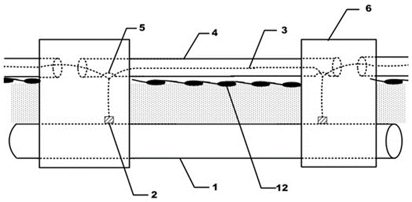
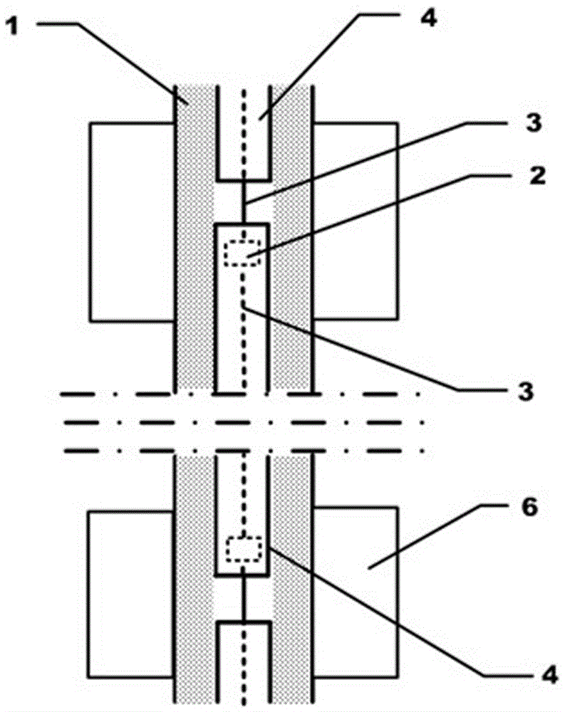
[0038] Such as figure 1 and figure 2 As shown, the sleeve-type underground pipeline leakage early warning system based on fiber gratings includes an underground pipeline 1 and an identification band 12 buried between the top of the underground pipeline 1 and the ground surface. Specifically, the identification band 12 is buried above the underground pipeline 1. 70cm; a protective sleeve 4 is laid above the identification tape 12, a sensor hole 5 is arranged on the outer wall of the bottom of the protective sleeve 4, a transmission optical cable 3 is arranged inside the protective sleeve 4, and a fiber grating sensor 2 is connected to the transmission optical cable 3. The grating sensor 2 extends out of the protective sleeve 4 through the sensor hole 5 and is fixed on the outer wall of the underground pipeline 1; a pit 6 is set at the position corresponding to each fiber grating sensor 2, and the pit 6 extends from the surface to the underground pipeline 1 side, the fiber gra...

Embodiment 2

[0052] The present invention also discloses a method for applying the above-mentioned casing-type underground pipeline leakage warning system based on optical fiber grating, including the following steps:

[0053] a. Lay the identification tape 12 between the top of the underground pipeline 1 and the ground surface, and lay the protective casing 4 on the identification tape 12. The outer wall of the bottom of the protective casing 4 is provided with a sensor hole 5, and the protective casing 4 is laid A transmission optical cable 3, the optical fiber grating sensor 2 is connected to the transmission optical cable 3, and the optical fiber grating sensor 2 protrudes out of the protective sleeve 4 through the sensor hole 5;

[0054] b. Set up a pit 6 at the corresponding position where the sensor 4 needs to be installed, the pit 6 extends from the surface to the outside of the underground pipeline 1, and the fiber grating sensor 2 reaches the outer wall of the underground pipeline...


PUM


Abstract

The invention discloses a telescoping underground pipeline leakage warning system on the basis of fiber gratings and a method implemented by the telescoping underground pipeline leakage warning system. The telescoping underground pipeline leakage warning system comprises an underground pipeline, fiber grating sensors, a transmission optical cable and mark belts. A protective sleeve sleeves the transmission optical cable, sensor holes are formed in the outer wall of the bottom of the protective sleeve, and the fiber grating sensors extend out of the protective sleeve via the sensor holes and are fixed onto the outer wall of the underground pipeline; the mark belts are buried between the upper side of the underground pipeline and the earth surface, bent portions are arranged on each mark belt at intervals, and chip assemblies are arranged on the mark belts; a well is arranged at a position corresponding to each fiber grating sensor, so that the fiber grating sensors and the transmission optical cable can be conveniently replaced and maintained. The telescoping underground pipeline leakage warning system and the method have the advantages that the fiber grating sensors include fiber grating strain sensors and fiber grating temperature sensors which are connected with one another in parallel, strain and the temperature of the outer wall of the underground pipeline are simultaneously monitored at each monitoring point, leakage events can be two-dimensionally responded, and accordingly leakage potential hazards of an underground pipe network can be accurately and effectively monitored.

Description

technical field [0001] The invention relates to an underground pipeline leakage early warning system, in particular to a casing type underground pipeline leakage early warning system based on optical fiber gratings, which is used to realize accurate automatic early warning of underground pipeline leakage and facilitates replacement and maintenance of the entire system. Background technique [0002] With the improvement of social economy and people's living standards, there are more and more various building groups, and the underground pipelines such as pipelines such as water, electricity, heating, and gas, electric wires and cables, and communication optical cables are extended underground. In order to prevent re-construction or burying other facilities when excavating trenches, the applicant applied for a utility model patent "underground pipeline identification belt" with the authorization announcement number CN2745074Y on November 25, 2004. When the excavator digs down, ...

Claims


Application Information

Patent Timeline
Patent Type & Authority Patents(China)
IPC IPC(8): F17D5/02
Inventor 解思亮赵华泽赵洪波
Owner QINGDAO HOUKE INFORMATION ENG
Learn More