Vibration sensor

A sensor and piezoelectric module technology, applied in the field of sensors to achieve the effect of improving image quality

Inactive Publication Date: 2014-07-09
ALTEK CORP
View PDF4 Cites 6 Cited by
  • Summary
  • Abstract
  • Description
  • Claims
  • Application Information

AI Technical Summary

Problems solved by technology

[0004] In view of the above-mentioned problems in the prior art, the object of the present invention is to provide a vibration sensor made of piezoelectric effect, so as to solve the problem that the conventional vibration sensor using piezoelectric material can only detect a single The problem of vibration displacement in the dimension direction

Method used


Image

  • Vibration sensor
  • Vibration sensor
  • Vibration sensor

Examples


Embodiment Construction

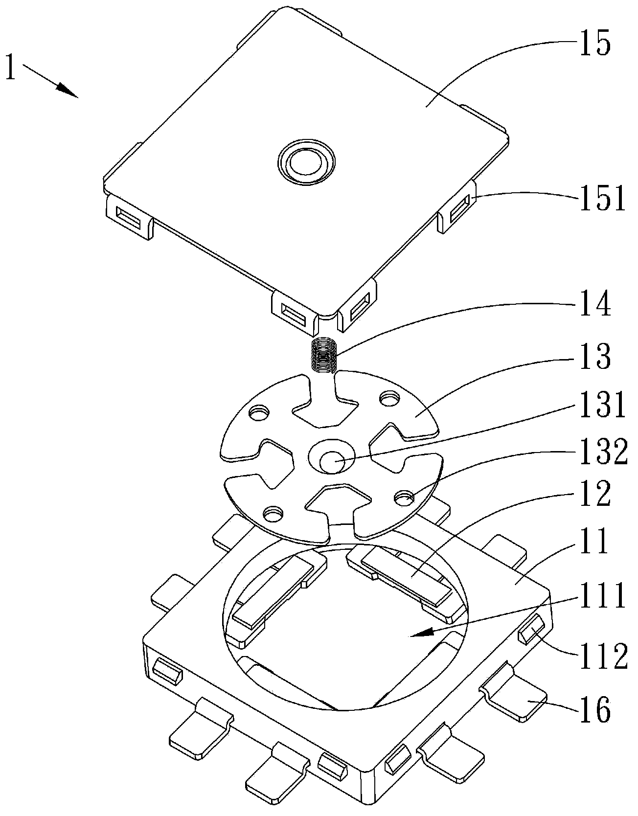
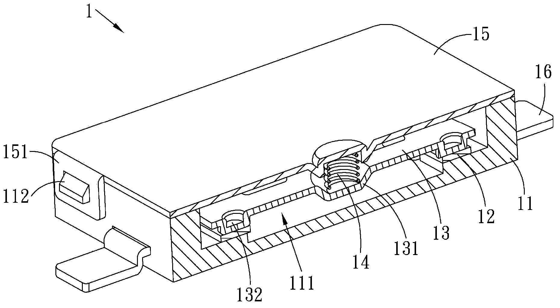
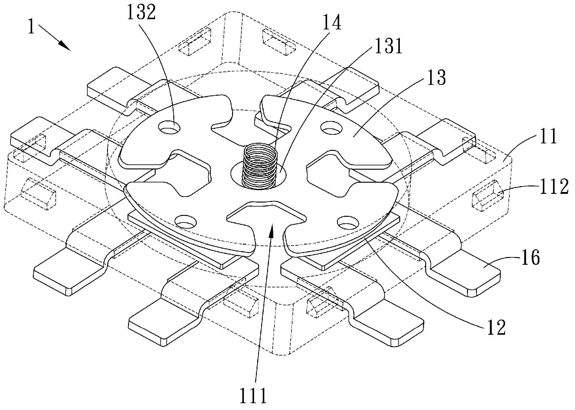
[0020] Please also refer to Figure 1 to Figure 3 , figure 1 It is an exploded view of an embodiment of the vibration sensor of the present invention, figure 2 It is a sectional view of an embodiment of the vibration sensor of the present invention, image 3 It is a perspective view of an embodiment of the vibration sensor of the present invention. As shown in the figure, the vibration sensor 1 of the present invention includes a housing 11 , a plurality of piezoelectric modules 12 , a joint module 13 , a stabilization module 14 , a plurality of sensing modules 16 and a cover 15 . The casing 11 includes a second connecting portion 112 , and an accommodating groove 111 is disposed in the casing 11 . A plurality of piezoelectric modules 12 are disposed in the accommodating groove 111 , and a geometric center of each piezoelectric module 12 corresponds to a central point of the accommodating groove 111 . The bonding modules 13 are disposed in the accommodating grooves 111 an...


PUM


Abstract

The invention discloses a vibration sensor which comprises a shell body, a plurality of piezoelectric modules, a connecting module and a stabilizing module. The shell body comprises a containing groove. The piezoelectric modules are arranged in the containing groove. The geometric centers of the piezoelectric modules correspond to the center point of the containing groove. The connecting module is arranged in the containing groove, and pressure is exerted on the piezoelectric modules evenly. The stabilizing module is arranged at the center point of the connecting module. The position of the stabilizing module corresponds to the center point of the containing groove. When the shell body shakes, the piezoelectric modules generate different high voltages and low voltages through the oblique pressure of the connecting module, then the vibration sensor and a processing module can operate in a cooperating mode, and the vibration displacement of the shell body is computed according to the voltage values.

Description

technical field [0001] The invention relates to a sensor, in particular to a vibration sensor which uses a piezoelectric material as a sensing interface and can effectively sense multi-dimensional displacement. Background technique [0002] The piezoelectric effect (Piezoelectric effect) is a phenomenon in which mechanical energy and electrical energy are exchanged, and its effects include two types: the positive piezoelectric effect (Dielectric piezoelectric effect) and the inverse piezoelectric effect (Conversepiezoelectric effect). Generally, the positive piezoelectric effect is mostly used in sensors (Sensor), because when the piezoelectric material is subjected to external mechanical stress, a charge (or electric field) proportional to the magnitude of the stress will be generated at both ends of the piezoelectric material, so it is suitable for applications on the sensor. On the contrary, the inverse piezoelectric effect is applicable to the actuator (Actuator), becau...

Claims


Application Information

Patent Timeline
IPC IPC(8): G01H11/08
Inventor 林资智黄毓承
Owner ALTEK CORP
Why Eureka
Try Eureka