A Method of Airflow Uniform Distribution Based on Numerical Calculation of Flow Field

A numerical calculation and uniform airflow technology, applied in the fields of energy, environmental protection, and chemical industry, can solve the problems of not being able to achieve the airflow distribution effect, affecting the efficiency of capturing PM2.5, and uneven airflow distribution in the downstream section of the bell mouth, etc.

Inactive Publication Date: 2016-11-30
SOUTHEAST UNIV
View PDF3 Cites 0 Cited by
  • Summary
  • Abstract
  • Description
  • Claims
  • Application Information

AI Technical Summary

Problems solved by technology

[0002] When the cross-sectional area of ​​the air flow channel changes, it is easy to cause uneven air distribution, such as mist eliminators, wet electrostatic precipitators, etc. Drastic changes occur, resulting in uneven distribution of air flow in the downstream section of the bell mouth
At present, some newly developed flue gas purification equipment such as wet desulfurization demisters and wet electrostatic precipitators have very high requirements for the uniformity of airflow distribution. The percentage of the entire channel section is required to reach more than 85%, and the uniformity of the flow field will significantly affect the efficiency of capturing PM2.5
[0003] In the prior art, the traditional adjustment method is usually adopted, that is, installing a deflector or an air distribution plate in the bell mouth or at the outlet of the bell mouth to adjust the uniformity of the air flow downstream of the bell mouth, although it can play a role in the uniformity of the air flow. It has a certain adjustment effect, but it cannot achieve the ideal air distribution effect, and cannot meet the requirements of some newly developed new equipment for controlling PM2.5 emissions.

Method used


Image

  • A Method of Airflow Uniform Distribution Based on Numerical Calculation of Flow Field
  • A Method of Airflow Uniform Distribution Based on Numerical Calculation of Flow Field

Examples


Embodiment Construction

[0018] The present invention will be further described below in conjunction with the accompanying drawings and specific embodiments.

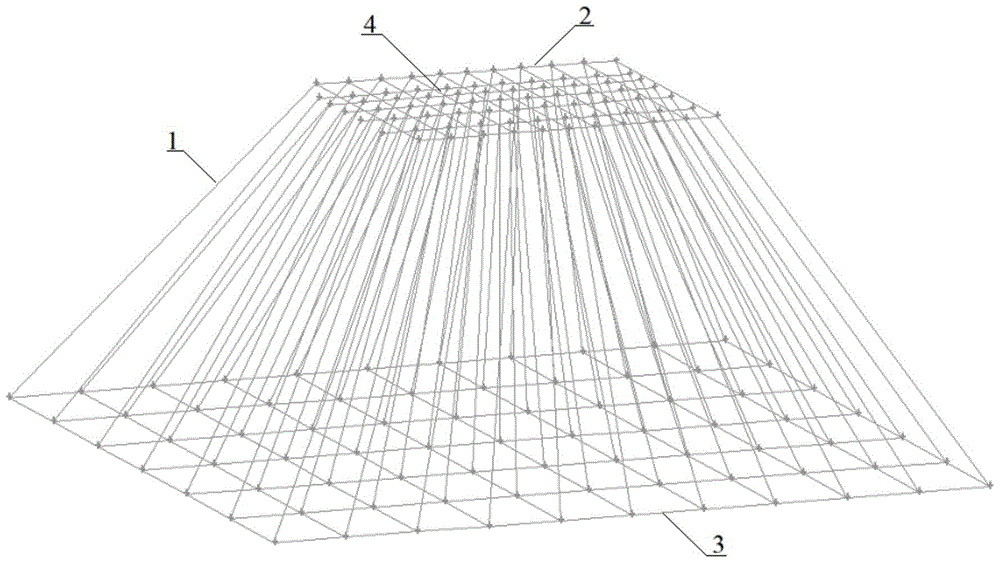
[0019] see figure 1 , a method for uniform distribution of airflow based on flow field numerical calculation of the present invention is provided with an air intake bell mouth 1, an air intake bell mouth entrance 2, an air intake bell mouth outlet 3, and a trapezoidal honeycomb structure guide grid 4.

[0020] The trapezoidal honeycomb structure guide grid 4 is arranged inside the air intake bell mouth 1, and the upper and lower parts of the trapezoidal honeycomb structure guide grid 4 are respectively connected with the air intake bell mouth inlet 2 and the air intake bell mouth outlet 3 .

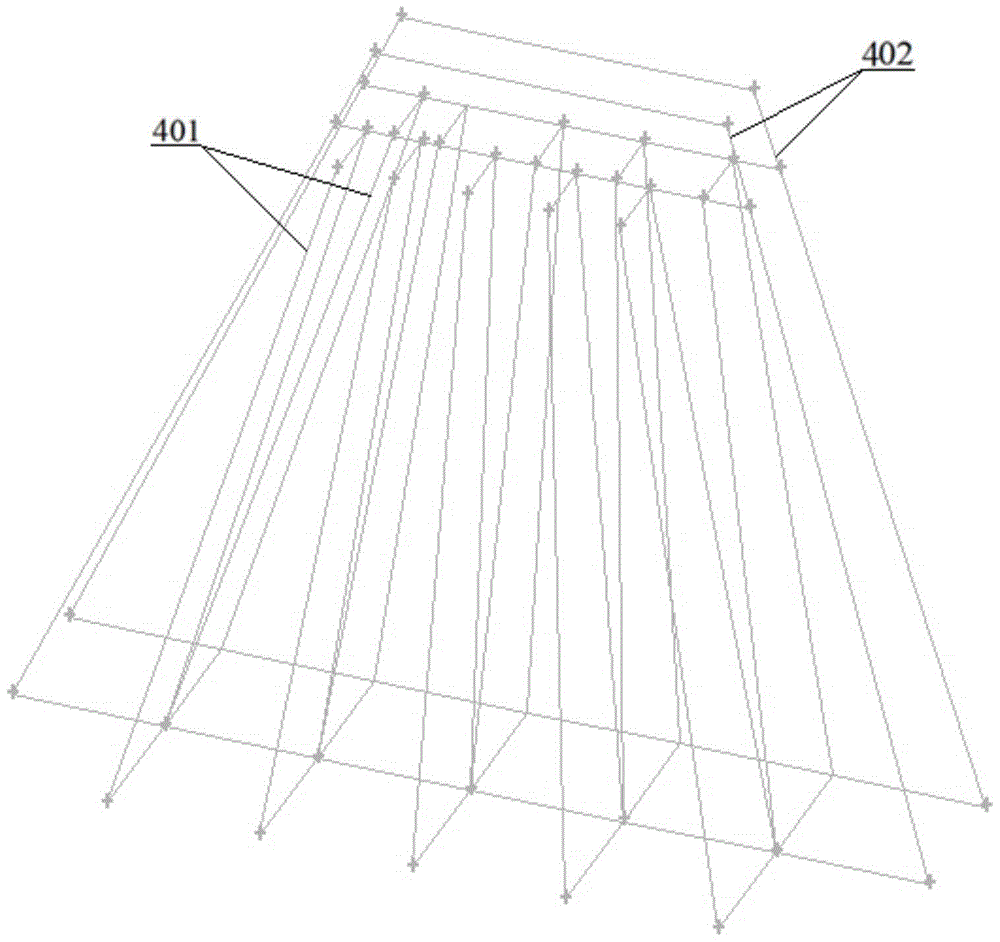
[0021] see figure 2 , the trapezoidal honeycomb structure diversion grid is composed of transverse partitions 401 and vertical partitions 402 intersecting each other perpendicularly. The longitudinal partition 402 divides the inner area of ​​the bell m...


PUM


Abstract

The invention discloses an airflow uniform distribution method based on numerical calculation of the flow field. A trapezoidal honeycomb structure diversion grid is arranged in a conventional bell mouth, and the airflow passes through the diversion grid from a narrower section channel to a wide section channel, combined with the flow field Numerical simulation of the flow field distribution of the air flow through the diversion grid, and obtain the flow distribution of each grid, and then obtain the deviation of the air flow of each grid channel from the average flow, and increase or decrease according to the size of the deviation For the entrance cross-sectional area of ​​the trapezoidal grid, the numerical simulation calculation of the flow field is carried out again. After several repetitions, the gas flow rate of each grid can be close to the same, so that the flow field of the wide-section channel can be evenly distributed. Utilizing the air flow uniform distribution method based on the numerical calculation of the flow field described in the present invention can reduce the flow velocity deviation on the target section to a very low range, and meet the needs of some engineering occasions that require high flow field uniformity. The method is effective and feasible.

Description

technical field [0001] The invention relates to a method for uniform distribution of air flow based on flow field numerical calculation, and relates to the technical fields of energy, environmental protection, chemical industry and the like. Background technique [0002] When the cross-sectional area of ​​the air flow channel changes, it is easy to cause uneven air distribution, such as mist eliminators, wet electrostatic precipitators, etc. Drastic changes occur, resulting in uneven distribution of air flow in the downstream section of the bell mouth. At present, some newly developed flue gas purification equipment such as wet desulfurization demisters and wet electrostatic precipitators have very high requirements for the uniformity of airflow distribution. The percentage of the entire channel section is required to reach more than 85%, and the uniformity of the flow field will significantly affect the efficiency of capturing PM2.5. [0003] In the prior art, the traditi...

Claims


Application Information

Patent Timeline
Patent Type & Authority Patents(China)
IPC IPC(8): G06F19/00
Inventor 袁竹林郝雅洁官蕾
Owner SOUTHEAST UNIV
Why Eureka
Try Eureka