A water jacket structure of an engine cylinder block

A technology for engine cylinders and cylinder blocks, which is applied to engine cooling, engine lubrication, engine components, etc., can solve problems such as low heat exchange efficiency of oil cooler fins, low heat exchange efficiency of cylinder liner, and poor cooling water fluidity. , to achieve the effect of reducing the volume of the cylinder liner, good consistency, and improving the flow rate

Active Publication Date: 2018-06-15
GUANGXI YUCHAI MASCH CO LTD
View PDF9 Cites 1 Cited by
  • Summary
  • Abstract
  • Description
  • Claims
  • Application Information

AI Technical Summary

Problems solved by technology

[0002] The water inlet pipe cavity of the existing engine cylinder block water jacket structure is large. Before the cooling water enters the cylinder jacket water jacket cavity and the oil cooler, each cylinder has a water inlet hole directly entering the cylinder head water jacket; at the same time, the cooling water Before entering the oil cooler, each cylinder has a water diversion hole connected to the water jacket chamber of the cylinder jacket; the flow of cooling water entering the water jacket chamber of each cylinder is small, the consistency of each cylinder is poor, and the heat exchange efficiency of the cylinder jacket is low
In addition, the oil cooler is arranged at the end of the water inlet pipe on the side of the cylinder block, and the cooling fins of the oil cooler are immersed in the water inlet pipe. Before the cooling water reaches the oil cooler, it has been diverted from the water jacket of each cylinder and the upper water port of the cylinder head. , The fluidity of the cooling water at the heat sink of the oil cooler is poor, the flow rate is low, and the heat transfer efficiency of the heat sink of the oil cooler is low

Method used


Image

  • A water jacket structure of an engine cylinder block
  • A water jacket structure of an engine cylinder block
  • A water jacket structure of an engine cylinder block

Examples


Embodiment Construction

[0025] The present invention will be further described below in conjunction with the specific embodiments in the accompanying drawings.

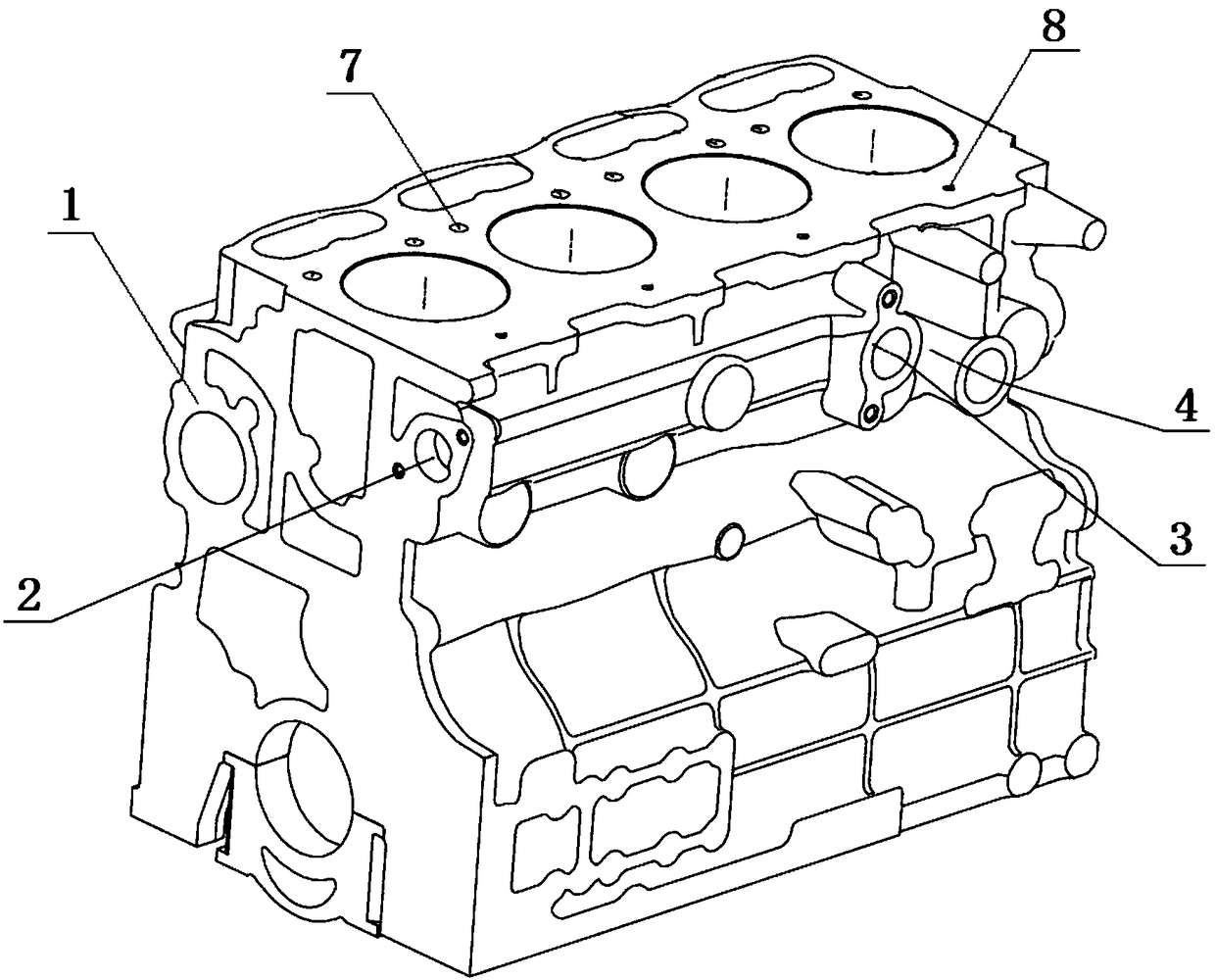
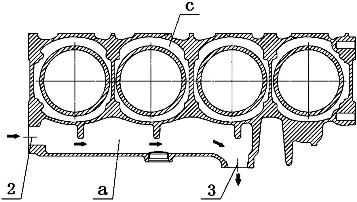
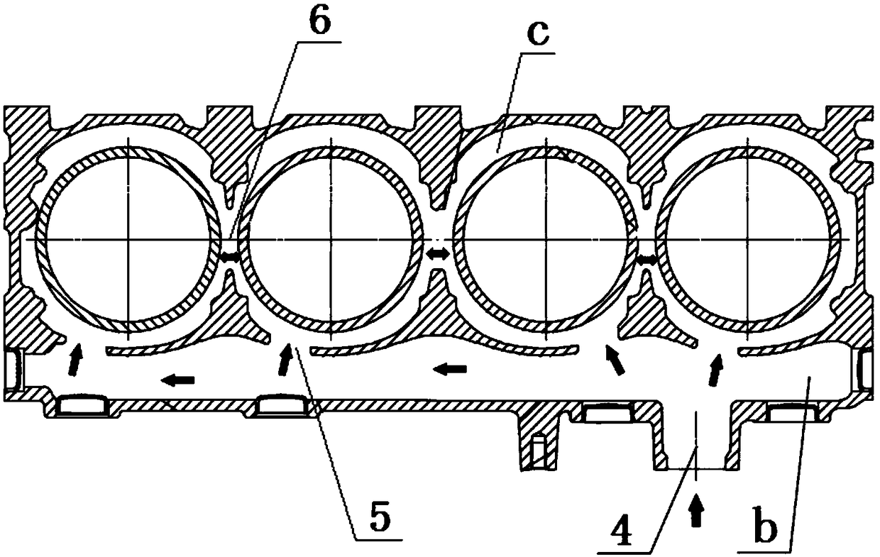
[0026] refer to Figure 1-7 , the water jacket structure of a kind of engine cylinder block of the present invention, comprises cylinder block 1, on the side of cylinder block 1, is provided with mutually independent oil cooler front waterway chamber a and rear waterway chamber b, in front waterway chamber a One end is provided with a cylinder body water inlet 2, the other end is provided with a front waterway chamber water outlet 3 that can be connected with an external oil cooler, and one end of the rear waterway chamber b is provided with a rear waterway chamber that can be connected with an external oil cooler Water inlet 4, the cooling water of the engine is pressed into the front water channel cavity a of the oil cooler through the cylinder block water inlet 2 of the cylinder block 1, and then all of it passes through the water outlet ...


PUM


Abstract

The invention discloses a water jacket structure of an engine air cylinder body. The water jacket structure comprises an air cylinder body, wherein a front water channel cavity and a rear water channel cavity of an engine oil cooler are arranged on one side of the air cylinder body and are mutually independent; an air cylinder body water inlet is arranged at one end of the front water channel cavity, and a front water channel cavity water outlet capable of being connected with the external mounting type engine oil cooler is arranged at the other end of the front water channel cavity; a rear water channel cavity water inlet capable of being connected with the external mounting type engine oil cooler is arranged at one end of the rear water channel cavity; each cylinder in the air cylinder body is provided with an air cylinder sleeve water jacket cavity; each air cylinder sleeve water jacket cavity is provided with a water jacket water guide hole communicated with the rear water channel cavity; and a communication hole for communicating the air cylinder sleeve water jacket cavities is arranged between the adjacent air cylinder sleeve water jacket cavities. The water jacket structure of the engine air cylinder body is simple; all cooling water of the engine passes through the external mounting type engine oil cooler; the flow of the cooling water is great and the flowing speed is high; and the consistency of all the cylinders is good and the cooling effect is good.

Description

technical field [0001] The invention relates to the technical field of engine cooling, more specifically, it relates to a water jacket structure of an engine cylinder block. Background technique [0002] The water inlet pipe cavity of the existing engine cylinder block water jacket structure is large. Before the cooling water enters the cylinder jacket water jacket cavity and the oil cooler, each cylinder has a water inlet hole directly entering the cylinder head water jacket; at the same time, the cooling water Before entering the oil cooler, each cylinder has a water diversion hole connected to the water jacket chamber of the cylinder jacket; the flow of cooling water into the water jacket chamber of the cylinder jacket of each cylinder is small, the consistency of each cylinder is poor, and the heat exchange efficiency of the cylinder jacket is low. In addition, the oil cooler is arranged at the end of the water inlet pipe on the side of the cylinder block, and the coolin...

Claims


Application Information

Patent Timeline
Patent Type & Authority Patents(China)
IPC IPC(8): F02F1/14F01P3/02F01M5/00
CPCF01M5/002F01P3/02F01P2003/021F02F1/14
Inventor 赵增亮肖耿陈剑涛胡国强钟秀俊
Owner GUANGXI YUCHAI MASCH CO LTD
Why Eureka
Try Eureka