Coil component

A technology of coil components and lead parts, which is applied in the direction of electrical components, transformers/inductor coils/windings/connections, transformers, etc., can solve the problem of insulation distance hindering the miniaturization of coil components, and achieve the increase of design freedom and the reduction of parts Number of pieces, easy effect of thinning

Active Publication Date: 2014-07-09
TDK CORPARATION +1
View PDF6 Cites 8 Cited by
  • Summary
  • Abstract
  • Description
  • Claims
  • Application Information

AI Technical Summary

Problems solved by technology

[0006] In such a coil component, it is necessary to lead out and connect the lead part of the secondary coil wound around the case to the secondary terminal formed at the end of the frame substra

Method used


Image

  • Coil component
  • Coil component
  • Coil component

Examples


no. 1 Embodiment approach

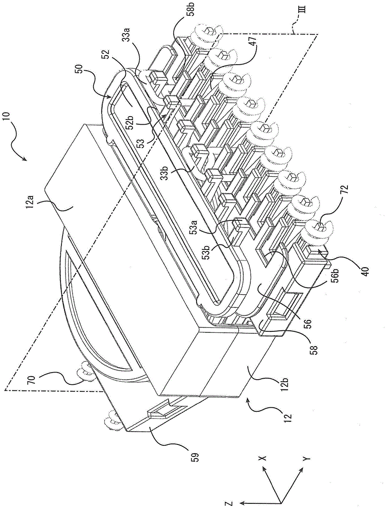
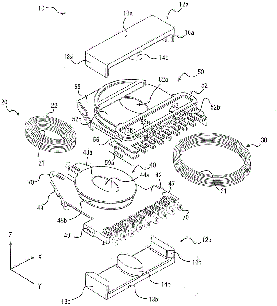
[0039] as a whole stereogram figure 1 and as an exploded perspective view figure 2 As shown, a coil component 10 according to an embodiment of the present invention has a core 12 , a bobbin 40 , a case 50 , a primary coil 20 , and a secondary coil 30 .

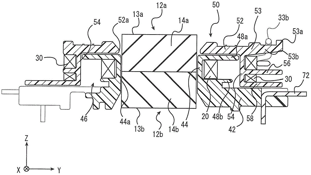
[0040] The core 12 of the coil component 10 is formed by forming a magnetic path through which a magnetic flux generated by a coil described later passes and assembling two separately formed members, that is, a first core 12a and a second core 12b. The first core 12 a and the second core 12 b have symmetrical shapes, and are joined to each other so as to sandwich the case 50 and the frame 40 from the vertical direction (the Z-axis direction in each figure).

[0041] like figure 1 As shown, the cores 12 each have a first core 12 a and a second core 12 b each having a substantially E-shaped longitudinal section (cross section including the X-axis and the Z-axis). like figure 2 As shown, each core 12a, 12b is composed of a ...

no. 2 Embodiment approach

[0077] Figure 5 It is a perspective view of the case 50a used for the coil component which concerns on 2nd Embodiment of this invention. The coil component according to the second embodiment is the same as the coil component 10 according to the first embodiment except that the shape of the upper flange protrusion 81 in the case 50a is different. Upper flange protrusion 81, with figure 1 The shown upper flange protrusion 53 does not have the locking portion 53a, but by appropriately securing the protruding length in the Y-axis direction, it is possible to prevent the lead wires 33a, 33b engaged with the upper flange protrusion 53 from occurring. fall off. The coil component according to the second embodiment can also obtain the same effects as those of the coil component according to the first embodiment.

no. 3 Embodiment approach

[0079] Image 6 It is a perspective view of the case 50b used for the coil component which concerns on 3rd Embodiment of this invention. The coil component according to the third embodiment is the same as the coil component 10 according to the first embodiment except that the shape of the upper flange protrusion 82 in the case 50b is different. The upper flange portion 82 has an upper groove portion 82c opened upward, and a locking portion 82a connected to the front end side of the upper groove portion 82c. Passing through the upper groove portion 82c when the lead portions 32a, 32b are engaged with the upper flange protrusion 82 prevents the lead portions 33a, 33b from falling off and stabilizes the positions of the lead portions 33a, 33b. The coil component according to the third embodiment can also obtain the same effects as those of the coil component according to the first embodiment.


PUM


Abstract

The invention provides a coil component which can reliably guarantee insulation distance and can connect a wiring part and a terminal. The coil component has a frame (40) which has a first hollow cylinder part (44) with a primary coil (20) winding on the outer periphery, and has a frame substrate which is provided with a primary terminal connected with the primary coil (20) and a secondary terminal (72), and is connected with the lower end of the first hollow cylinder part; a housing (50) which has a second hollow cylinder part (54) winding on the outer periphery of the primary coil and having the secondary coil on the periphery, a lower flange part (58) connecting to the lower end of the second hollow cylinder part in a manner of arranging on the frame substrate, and an upper flange (52) connected to the upper end of the second hollow cylinder part; and at least one wire leading part (32a) in the secondary coil, being connected to the secondary terminal after being pulled out from the second hollow cylinder part to the upper flange.

Description

technical field [0001] The present invention relates to a coil component suitable for use as a resonance transformer or the like, for example. Background technique [0002] Coil components are used in various applications in various electrical products. For example, in driving a backlight of a liquid crystal display, etc., in order to obtain a high voltage, a resonant transformer for an inverter is used. [0003] In addition to electrical characteristics such as generation of appropriate leakage inductance, a resonant transformer is also required to achieve external shape such as thinning. Conventionally, in order to respond to such demands, a coil component of a divided structure has been proposed in which the axial direction of the core is parallel to the installation surface, and the primary coil and the secondary coil are separately arranged along the axial direction of the core. In addition, the divided structure of the coil component has the advantage of being relati...

Claims


Application Information

Patent Timeline
IPC IPC(8): H01F38/08H01F27/30H01F30/00
Inventor 前田浩山田稔丰田晃正黄基浩
Owner TDK CORPARATION
Why Eureka
Try Eureka