Milling cutter

A technology for milling cutters and cutting blades, which is applied in milling cutters, manufacturing tools, milling machine equipment, etc. It can solve problems such as safety and quality accidents, affect tool accuracy, limit tool speed and cutting efficiency, and achieve accurate positioning and high cutting efficiency. Effect

Active Publication Date: 2014-07-16
ZHUZHOU CEMENTED CARBIDE CUTTING TOOLS CO LTD
View PDF6 Cites 3 Cited by
  • Summary
  • Abstract
  • Description
  • Claims
  • Application Information

AI Technical Summary

Problems solved by technology

[0002] The rotary slot milling cutter is equipped with an indexable insert, which must be fixed on the disc body of the milling cutter during use. In the prior art, the insert is usually radially pressed inward from the periphery of the cutter body by a self-compressing method. , the blade is axially loaded into the opening of the disc body or taken out. The radial component force direction of the cutter body’s pressing force on the blade is consistent with the centrifugal force direction when the cutter rotates. When the resultant force of the radial component force and centrifugal force is greater than the blade’s When the friction force is high, the blade will be thrown out, causing safety and quality accidents, thus limiting the speed and cutting efficiency of the tool. At the same time, the assembly and positioning of the blade when it is loaded into the disc body is not accurate, which affects the accuracy of the tool.

Method used


Image

  • Milling cutter
  • Milling cutter
  • Milling cutter

Examples


Embodiment Construction

[0030] The present invention will be further described in detail below in conjunction with the accompanying drawings and specific embodiments.

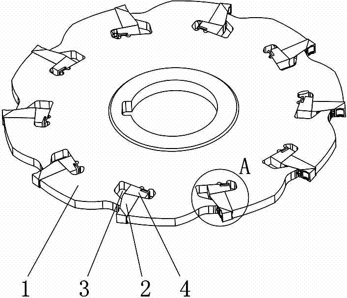
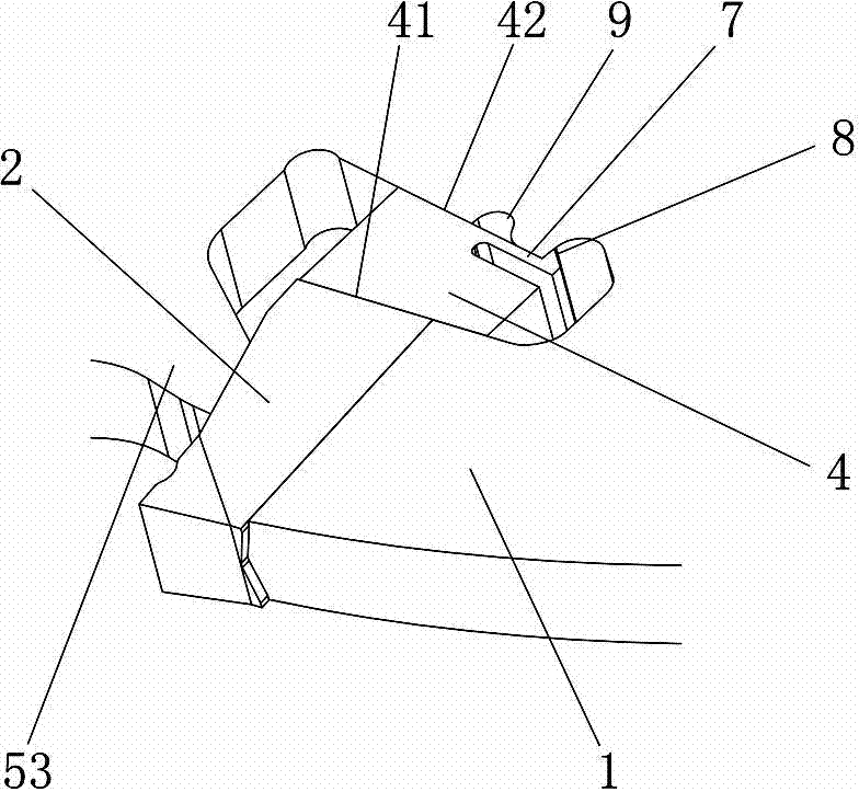
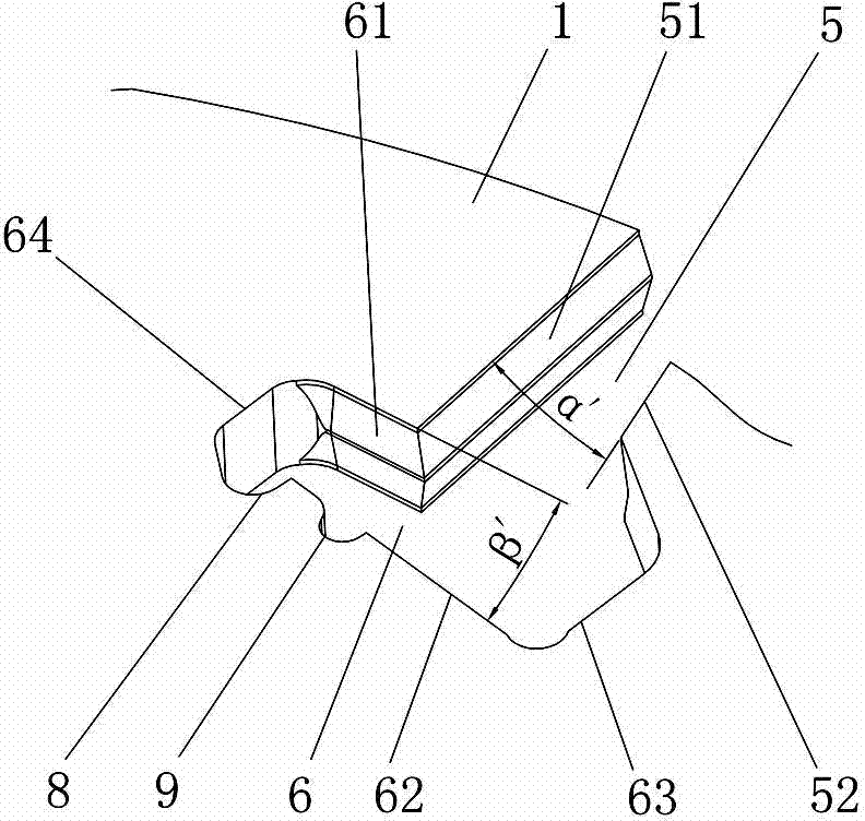
[0031] Figure 1 to Figure 11 An embodiment of the milling tool of the present invention is shown, the milling tool comprises a disc-shaped cutter body 1, a cutting blade 2 and a sipe 3 opened on the outer edge of the disc-shaped cutter body 1, the sipe 3 includes a blade clamping groove 5 and the briquetting mounting groove 6, the bottom surface 21 and the top surface 22 of the cutting blade 2 abut against the first clamping surface 51 and the second clamping surface 52 of the blade clamping groove 5 respectively, and the bottom surface 21 and the top surface 22 face the plate The radially extending planes outside the disc-shaped cutter body 1 intersect to form an included angle α, and the first clamping surface 51 and the second clamping surface 52 intersect to form an included angle α' to the radially extending planes outside the d...


PUM


Abstract

The present invention discloses a milling cutter, which comprises a disk-like cutter body, cutting blades and cutter grooves arranged on the outer edge of the disk-like cutter body, wherein the cutter groove comprises a cutting blade clamping groove and a pressing block installation groove, the bottom surface and the top surface of the cutting blade respectively bear against the first clamping surface and the second clamping surface of the cutting blade clamping groove, the radially-extending surfaces of the bottom surface and the top surface toward the external of the disk-like cutter body intersect so as to form an included angle alpha, the radially-extending surfaces of the first clamping surface and the second clamping surface toward the external of the disk-like cutter body intersect so as to form an included angle alpha', the alpha' is more than or equal to the alpha, and pressing blocks for radially and tightly pressing the cutting blades are arranged inside the pressing block installation grooves. The milling cutter has advantages of safety, reliability, accurate assembly positioning, high cutting efficiency and the like.

Description

technical field [0001] The present invention relates to cutting tools, in particular to a milling tool. Background technique [0002] The rotary slot milling cutter is equipped with an indexable insert, which must be fixed on the disc body of the milling cutter during use. In the prior art, the insert is usually radially pressed inward from the periphery of the cutter body by a self-compressing method. , the blade is axially loaded into the opening of the disc body or taken out. The radial component force direction of the cutter body’s pressing force on the blade is consistent with the centrifugal force direction when the cutter rotates. When the resultant force of the radial component force and centrifugal force is greater than the blade’s When there is too much friction, the blade will be thrown out, causing safety and quality accidents, thus limiting the speed and cutting efficiency of the tool. At the same time, the assembly and positioning of the blade when it is loaded...

Claims


Application Information

Patent Timeline
Patent Type & Authority Applications(China)
IPC IPC(8): B23C5/08
Inventor 王东海刘敏易为王云志
Owner ZHUZHOU CEMENTED CARBIDE CUTTING TOOLS CO LTD
Why Eureka
Try Eureka