Deburring device for wheel back cavity

A deburring and cavity backing technology, which is applied in the direction of grinding machines, metal processing equipment, grinding/polishing equipment, etc., can solve the problems of poor versatility, inconvenient use, and affecting production efficiency of brushing and burring machines, and achieve safe, stable and universal performance. Strong performance and high degree of automation

Active Publication Date: 2014-07-16
CITIC DICASTAL
View PDF7 Cites 10 Cited by
  • Summary
  • Abstract
  • Description
  • Claims
  • Application Information

AI Technical Summary

Problems solved by technology

For the brushing and burring process, the traditional brushing and burring machine has poor versatility. One device can only adapt to one size of wheel. For wheels of different sizes, only the fixture and brush can be replaced at the same time. productivity

Method used


Image

  • Deburring device for wheel back cavity
  • Deburring device for wheel back cavity
  • Deburring device for wheel back cavity

Examples


Embodiment Construction

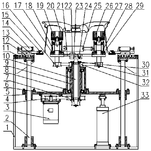
[0017] The details and working conditions of the specific device proposed according to the present invention will be described below in conjunction with the accompanying drawings.

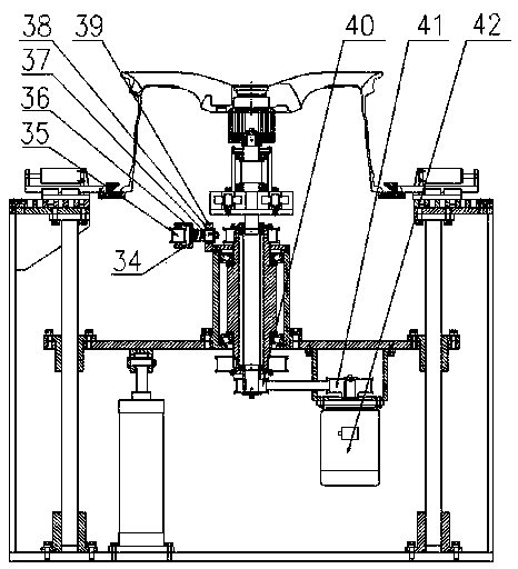
[0018] The device consists of a frame 1, a lower guide column 2, a left motor 3, a left pulley I4, a lower guide sleeve 5, a lifting plate 6, a lower pulley I7, a lower bearing seat 8, a hollow shaft 9, a rotating shaft 10, and a scale plate 11. Bottom plate 12, guide rail 13, clamping cylinder 14, pressure block 15, left pulley II 16, left base plate 17, left bearing seat 18, left shaft 19, left brush 20, rack 21, rack slide 22, Support plate 23, gear 24, servo electric cylinder 25, right brush 26, right shaft 27, right bearing seat 28, right base plate 29, anti-loosening ring 30, right pulley II 31, upper pulley 32, lifting cylinder 33, support Frame 34, tension pulley 35, sliding column 36, spring 37, sliding sleeve 38, side plate 39, lower pulley II 40, right pulley I 41 and right motor 42, fou...


PUM


Abstract

The invention discloses a deburring device for a wheel back cavity. The deburring device is composed of a rack, a gear, a gear rack, motors, a servo electric cylinder and the like. A left hairbrush and a right hairbrush move synchronously and are adjusted to suitable positions through the servo electric cylinder, the gear and the gear rack, and while the left motor drives a hollow shaft to rotate, the left hairbrush and the right hairbrush rotate. Through a lower guide post, a lifting cylinder enables the two rotating hairbrushes to make contact with the back cavity of a rim, and meanwhile the right motor drives a rotating shaft and the two hairbrushes to rotate around the center of a wheel. The positions of the two hairbrushes and the position of a clamp can be conveniently and rapidly adjusted according to wheels in different sizes, and meanwhile the deburring device has the advantages of being advanced in technology, high in automation degree and generality and safe and reliable in performance.

Description

technical field [0001] The invention relates to a deburring device, in particular to a deburring device capable of adjusting the size. Background technique [0002] The vast majority of aluminum alloy wheel manufacturers are in mixed production, that is, wheels of different sizes are circulating in various processes on the production line at the same time. For the brushing and burring process, the traditional brushing and burring machine has poor versatility. One device can only adapt to one size of wheel. For wheels of different sizes, only the fixture and brush can be replaced at the same time. production efficiency. Therefore, in order to enhance versatility and improve production efficiency, more and more wheel manufacturers are constantly looking for a wheel deburring machine that can adapt to different sizes and is easy to replace the fixture. Contents of the invention [0003] The object of the present invention is to provide a wheel deburring device, which can qu...

Claims


Application Information

Patent Timeline
Patent Type & Authority Applications(China)
IPC IPC(8): B24B9/04
CPCB24B9/04
Inventor 薛博文郭建东刘会莹王永宁朱志华李昌海
Owner CITIC DICASTAL
Why Eureka
Try Eureka