
Three-dimensional ink-jet printer for sand molds

A three-dimensional printer and sand mold technology, applied in ceramic molding machines, manufacturing tools, etc., can solve the problems of inconvenient operation, inability to lay sand layers of uniform thickness, and long time.

Inactive Publication Date: 2014-07-16
SUZHOU MEIMAI RAPID MFG TECH
View PDF6 Cites 9 Cited by
  • Summary
  • Abstract
  • Description
  • Claims
  • Application Information

AI Technical Summary

Problems solved by technology

[0002] When printing a sand mold with a 3D printer, it is necessary to lay the sand particles of the pre-mixed curing agent on the workbench layer by layer according to the thickness of each section. For each layer of sand particles, the print head will spray the binder on the upper layer through the shape controlled by the program. (barking resin), print a section, but the sand layer is often not able to lay the sand layer into a sand layer with a consistent thickness during the sanding process, and because of the limitation of the number of print heads, it often takes a long time to print a section , after the printing is finished, it is necessary to disassemble some parts of the printer to recover the excess sand particles, which is inconvenient to operate

Method used


Image

  • Three-dimensional ink-jet printer for sand molds
  • Three-dimensional ink-jet printer for sand molds
  • Three-dimensional ink-jet printer for sand molds

Examples


Embodiment Construction

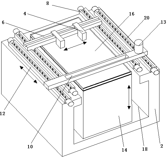
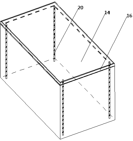
[0017] The present invention will now be further described in detail in conjunction with the accompanying drawings and embodiments. These drawings are all simplified schematic diagrams, only illustrating the basic structure of the present invention in a schematic manner, so it only shows the composition related to the present invention.

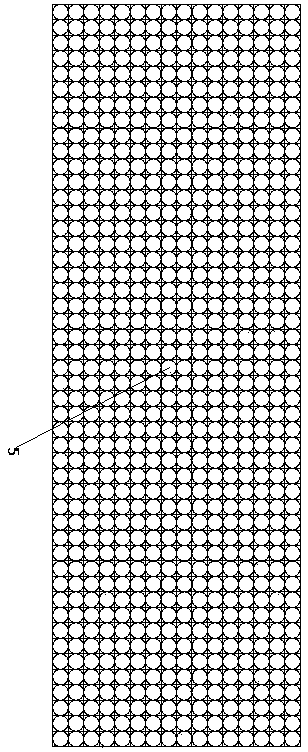
[0018] Such as figure 1 , figure 2 , image 3 As shown, an inkjet sand-type three-dimensional printer includes two sets of print head longitudinal rails 8 and sand bin longitudinal rails 12 arranged in parallel on the upper part of the frame 2, and are vertical to the print head longitudinal rails 8 and sand bin longitudinal rails 12 respectively. Connect the printing head rail 6 and the sand shop 10 at both ends, and a drawing chamber 18 is provided at the bottom of the frame 2, and a working cylinder 14 can be drawn in the drawing chamber 18, and a workbench 16 is arranged on the top of the working cylinder 14.

[0019] In order to impro...


PUM


Abstract

The invention relates to a three-dimensional ink-jet printer for sand molds. A pulling cavity is formed in the lower portion of a machine frame, and two parallel printing head longitudinal rails and two parallel sand bin longitudinal rails are arranged on the plane of the upper portion of the machine frame. A printing head cross rail perpendicularly stretches across the two printing head longitudinal rails and is provided with at least one printing head connected into a sliding groove, and a paving sand bin perpendicularly stretches across the two sand bin longitudinal rails. A plurality of programming spraying heads are densely arrayed on the bottom face of the printing head, the paving sand bin is provided with a vibrator, a working cylinder is arranged in the pulling cavity, and a worktable is connected with the top of the working cylinder through a lead screw. Because the printer is provided with the two printing heads, printing time is shortened, and bonding uniformity of each bonding agent layer and sand particles is improved; because the paving sand bin is provided with the vibrator, the uniformity of thicknesses of sand paving layers is improved; a transmission system driven by the lead screw can improve motion stability and accuracy; the drawer-type working cylinder can simplify the sand particle recycling step, the sand molds can be conveniently taken out, time is saved, and materials are prevented from being wasted.

Description

technical field [0001] The invention relates to a three-dimensional printer, in particular to an inkjet sand-type three-dimensional printer. Background technique [0002] When printing a sand mold with a 3D printer, it is necessary to lay the pre-mixed curing agent sand on the workbench layer by layer according to the thickness of each section. For each layer of sand, the print head will spray the binder on the upper layer through the shape controlled by the program. (barking resin), print out a section, but the sand layer is often not able to lay the sand layer into a sand layer with a consistent thickness during the sanding process, and because of the limitation of the number of print heads, it often takes a long time to print a section , After printing, it is necessary to disassemble some parts of the printer to recover the excess sand, which is inconvenient to operate. Contents of the invention [0003] The invention overcomes the shortcomings of the prior art and ...

Claims


Application Information

Patent Timeline
Patent Type & Authority Applications(China)
IPC IPC(8): B28B1/00
CPCB28B1/001
Inventor 金天拾
Owner SUZHOU MEIMAI RAPID MFG TECH
Learn More