Carrying trolley for extinguishment shooting device

A technology for carrying trolleys and launching devices, which is applied in the directions of manual conveying devices, transportation and packaging, etc. It can solve problems such as potential safety hazards, affecting fire fighting efficiency, inconvenient transfer of fire fighting launching devices, etc., and achieves the effect of ensuring stability and improving fire fighting efficiency

Inactive Publication Date: 2014-07-16
CHENGDU LINGCHUAN SPECIAL IND
View PDF7 Cites 2 Cited by
  • Summary
  • Abstract
  • Description
  • Claims
  • Application Information

AI Technical Summary

Problems solved by technology

[0003] The purpose of the present invention is to provide a trolley for carrying the fire extinguishing and launching device, which solves the problem that the tr

Method used


Image

  • Carrying trolley for extinguishment shooting device
  • Carrying trolley for extinguishment shooting device
  • Carrying trolley for extinguishment shooting device

Examples


Embodiment 1

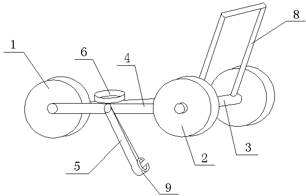
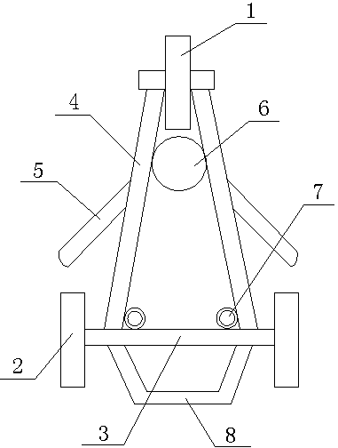
[0015] like figure 1 , figure 2 As shown, the carrying trolley of the fire extinguishing and launching device described in this embodiment includes a front wheel 1 and two rear wheels 2, the bearings of the two rear wheels 2 are connected by a cross bar 3, and the two ends of the bearing of the front wheel 1 are respectively connected by a Long bar 4 and cross bar 3 are fixed, and two long bars 4 and cross bar 3 form a triangular support, and every long bar 4 and cross bar 3 junctions are all provided with a ring 7, near the two front wheels 1 A drum 6 is arranged between the two inclined bars 4, a push handle 8 is arranged on the said cross bar 3, a rocking arm 5 is respectively arranged on each said inclined bar 4, and the rocking arm 5 is hingedly connected with the inclined bar 4, A collet 9 is provided on the end of the rocker arm 5 away from the inclined rod 4 .

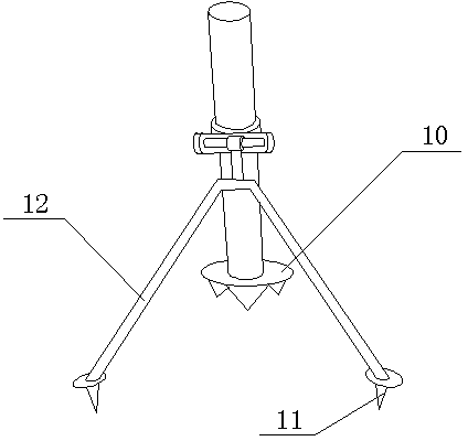
[0016] like image 3 Shown is a schematic diagram of the structure of the fire extinguishing launcher. D...

Embodiment 2

[0018] In this embodiment, on the basis of Embodiment 1, the installation angle of the push handle 8 is limited, and the angle between the plane where the push handle 8 is located and the vertical plane in this embodiment is 30-45 degrees, so that the force on the push cart is more reasonable , the movement is more stable, which is conducive to the cart to reach the fire extinguishing launch location quickly and smoothly.

Embodiment 3

[0020] In this embodiment, on the basis of Embodiment 1, the collet 9 is defined as follows: the collet 9 in this embodiment is made of elastic rubber, so that the collet 9 can not only hold the function, it is convenient to take and place the chuck, and at the same time, it can avoid damage to the support rod of the fire extinguishing launching device.


PUM


Abstract

The invention discloses a carrying trolley for an extinguishment shooting device. The carrying trolley comprises a supporting rod, a lantern ring, a U-shaped groove, a horizontal shaft, a round ring and a connecting rod. The U-shaped groove is fixed in the outer surface of the lantern ring, the horizontal shaft is fixed in the U-shaped groove, the round ring is connected to the horizontal shaft in a penetrating mode and fixedly connected with the connecting rod, and the connecting rod is fixedly connected with the supporting rod. The supporting rod is of a V-shaped structure, and the middle point position of the supporting rod is fixedly connected with the connecting rod. Buckets are respectively arranged at the two ends of the supporting rod, conical insertion rods are arranged below the buckets, and a loosening structure is arranged between the two buckets. The loosening structure comprises a pedal rod, the middle of the pedal rod is sunken downwards to form a notch, the two ends of the pedal rod are bent downwards, arc-shaped fork heads are respectively fixed to the two ends of the pedal rod, and the two ends of the pedal rod are connected with the buckets in a hinged mode. According to the structure, a support can be pulled out easily, and the arrangement and storage efficiency of the extinguishment shooting device can be improved.

Description

technical field [0001] The invention relates to the field of transportation of fire extinguishing and launching devices, in particular to a trolley for carrying the fire extinguishing and launching devices. Background technique [0002] Forest fire is a sudden, destructive, and difficult to deal with natural disasters. The intensity of forest fires varies. High-intensity fires have rising convective smoke columns and vortices, which can carry fire materials and spread to distant places in front of the fire. The fire is difficult to extinguish, and firefighters cannot approach at close range. At this time, they can only use long-range fire extinguishing bombs to extinguish the fire. The current fire extinguishing and launching device has its own bracket, and the bottom of the bracket is provided with a structure such as a steel nail or a tapered column, so that the bracket can be inserted into the soil to ensure that when the fire extinguishing bomb is fired, the bracket can...

Claims


Application Information

Patent Timeline
IPC IPC(8): B65G7/02
Inventor 胡辰洪侯栋黄柳志
Owner CHENGDU LINGCHUAN SPECIAL IND
Why Eureka
Try Eureka