Concrete bypassing preventing device with pulp stopping plates and concrete bypassing preventing construction method for H-shaped steel joint of wall chase of underground continuous wall

A technology of underground diaphragm wall and anti-slip board, which is applied to artificial islands, water conservancy projects, underwater structures, etc., to achieve the effect of simple construction process, low cost and good anti-flow effect

Inactive Publication Date: 2014-07-16
广西建工第五建筑工程集团有限公司
View PDF7 Cites 12 Cited by
  • Summary
  • Abstract
  • Description
  • Claims
  • Application Information

AI Technical Summary

Problems solved by technology

[0011] The object of the present invention is to provide an implementable "concrete circumvention prevention device for the H-shaped steel joint of the underground diaphragm wall groove section and its construction method for preventing concrete circumvention", so as to overcome the "underground diaphragm wall joint anti-circumvention device" To solve the problem of concrete flow around the H-shaped steel joint of the underground diaphragm wall groove section during the construction of the ground connection wall

Method used


Image

  • Concrete bypassing preventing device with pulp stopping plates and concrete bypassing preventing construction method for H-shaped steel joint of wall chase of underground continuous wall
  • Concrete bypassing preventing device with pulp stopping plates and concrete bypassing preventing construction method for H-shaped steel joint of wall chase of underground continuous wall
  • Concrete bypassing preventing device with pulp stopping plates and concrete bypassing preventing construction method for H-shaped steel joint of wall chase of underground continuous wall

Examples


Embodiment 1

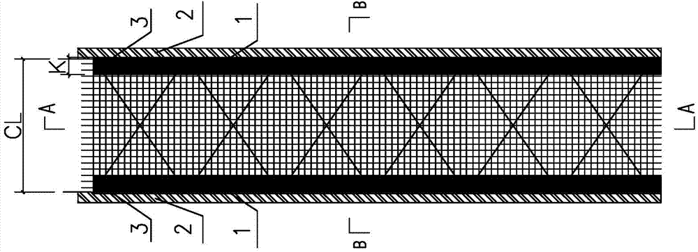
[0046] A device for preventing concrete flow-around by a grout-stopping plate of an H-shaped steel joint in a groove section of an underground continuous wall, comprising two grout-stopping plates 1 respectively arranged on the flange plates of I-shaped water-stop steel plates 2 of the ground connection wall, the grout-stopping plates 1. One end is fixedly connected with the I-shaped water-stop steel plate flange plate, and the other end is a free end. One of the slurry-stop plates 11 is fixedly connected with the inner side of the lower flange plate 21 of the I-shaped water-stop steel plate, and the other slurry-stop plate 12 It is fixedly connected with the outer side of the upper flange plate 22 of the I-shaped waterproof steel plate (see figure 1 , Figure 4-Figure 5 ).

[0047] The grout stopper 1 is a galvanized iron sheet with a thickness of 0.5mm and a length greater than 500mm of the reinforcement cage, the width K of the grout stopper is 500mm, and a steel bar with...

Embodiment 2

[0050] A construction method for preventing the flow of concrete by the H-shaped steel joint slurry plate of the groove section of the underground continuous wall. The method for preventing the concrete bypass flow construction of the H-shaped steel joint slurry plate, which includes the following steps (see Figure 4 , Figure 5 ):

[0051] A. Material preparation: Prepare the pulp stop board and the pulp stop board bead, choose the galvanized iron sheet with a thickness of 0.5mm and a length greater than the length of the steel cage 400-600mm as the pulp stop board, the width K of the pulp stop board is 400-600mm, and the diameter φ= The 18mm steel bar is used as the bead 3 of the grout plate;

[0052] B. Set the inner side of the H-shaped steel lower flange plate: first lay the inner side of the H-shaped steel lower flange plate 21 on both sides of the steel mesh sheet, lay the anti-slip plate 11, and overlap the flange plate 21 by 100mm, and then arrange the reinforceme...


PUM


Abstract

A concrete bypassing preventing device provided with pulp stopping plates and used for an H-shaped steel joint of a wall chase of an underground continuous wall comprises two pulp stopping plates, wherein the two pulp stopping plates are respectively arranged on flange plates of an H-shaped water stopping steel plate of the underground continuous wall; one ends of the pulp stopping plates are fixedly connected with the flange plates of the H-shaped water stopping steel plate; the other ends of the pulp stopping plates are free ends; one of the pulp stopping plates is fixedly connected with the inside of one of the flange plates of the H-shaped water stopping steel plate; the other pulp stopping plate is fixedly connected with the outside of the flange plate on the other side of the H-shaped water stopping steel plate; the pulp stopping plates are galvanized iron sheets; the thicknesses of the galvanized iron sheets are 0.5mm; and the lengths of the galvanized iron sheets are longer than a reinforcement cage by about 500mm. During construction, the pulp stopping plate on the inner side of the flange plate on the lower side of the H-shaped water stopping steel plate is arranged at first, then the pulp stopping plate on the outer side of the flange plate on the upper side of the H-shaped water stopping steel plate is arranged, the free ends of the pulp stopping plates are not required to be connected with reinforcing steel bars, so that the free ends of the pulp stopping plates can be opened without limitation during pouring of concrete, and can be totally opened according to designed requirements, the poured concrete is effectively prevented from bypassing and entering an H-shaped steel web plate, and the problem of bypassing of the concrete at the joint can be well solved.

Description

technical field [0001] The invention relates to a building construction method and device, in particular to an anti-concrete bypass flow prevention device for an H-shaped steel joint slurry plate of an underground continuous wall groove section and a construction method for preventing concrete bypass flow. Background technique [0002] Under normal circumstances, the protective layer of the main reinforcement of the underground diaphragm wall is 50mm to 70mm, so the concrete may flow around the outside of the H-shaped steel and enter the adjacent unit grooves during the pouring process due to the lack of protection. Later excavation, punching, cleaning, etc. caused difficulties. [0003] In order to prevent the concrete from flowing around the outside of the H-shaped steel and entering into the H-shaped steel and adjacent unit grooves, the current construction method is: paste plastic foam boards within the entire length of the H-shaped steel, and fill sandbags or mud bags; ...

Claims


Application Information

Patent Timeline
Patent Type & Authority Applications(China)
IPC IPC(8): E02D29/16E02D29/02
Inventor 覃培何显文黄玲林俊玉启海
Owner 广西建工第五建筑工程集团有限公司
Why Eureka
Try Eureka