Self-locking installation components for non-destructive assembly and disassembly of dense panels

A technology of installing components and close-fitting, which is applied in the fields of construction engineering, decoration engineering, and installation engineering, can solve the problems of inconvenient installation and disassembly, and cannot be disassembled separately, and achieve the effect of eliminating installation errors.

Active Publication Date: 2015-12-02
SHENZHEN YIJINGSHENG DECORATION ENG
View PDF7 Cites 0 Cited by
  • Summary
  • Abstract
  • Description
  • Claims
  • Application Information

AI Technical Summary

Problems solved by technology

[0002] When installing plate materials into the walls and ceilings, such as installing wooden veneers or other anti-magnetic plates, the blocks are densely assembled, usually it is necessary to punch holes in the walls, ceilings and other substrates, and use expansion bolts to attach the hook From the slot plate to the base, the hooks are installed on the back of the plate, and the hooks are hung in sequence along a certain direction. Before installation, the hole position of the expansion bolt in the base and the installation of the hook slot must be accurately positioned, otherwise, there will be no later stage. It must be dismantled and re-installed for calibration. Because it is in the form of buckle installation in sequence, a certain plate cannot be disassembled separately, which has the disadvantage of inconvenient installation and disassembly.

Method used


Image

  • Self-locking installation components for non-destructive assembly and disassembly of dense panels
  • Self-locking installation components for non-destructive assembly and disassembly of dense panels
  • Self-locking installation components for non-destructive assembly and disassembly of dense panels

Examples


Embodiment Construction

[0014] In order to enable those skilled in the art to better understand the technical solution, the present invention will be further described in detail below in conjunction with the accompanying drawings and embodiments.

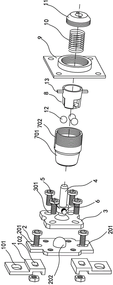
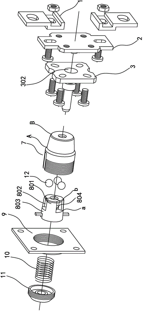
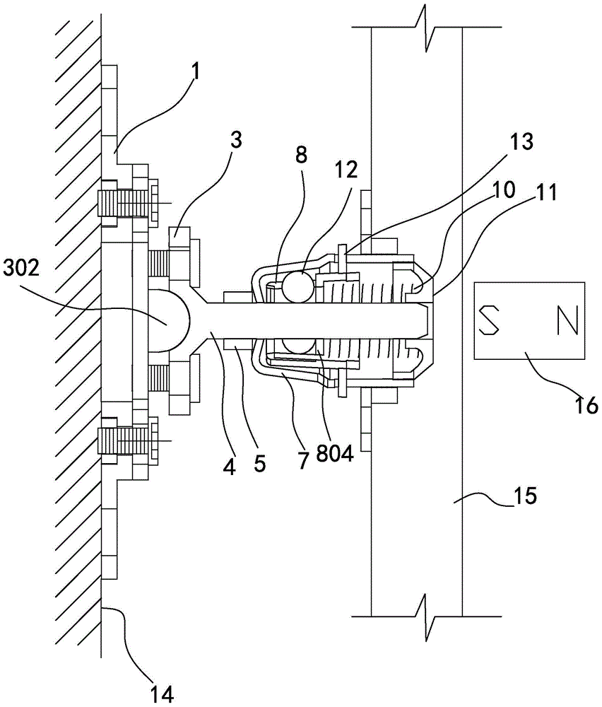
[0015] Such as Figure 1-2 As shown, the self-locking installation member that the plates are assembled and disassembled without damage includes a separably connected base and a movable lock sleeve; the base includes: two fixed plates 1 with mounting holes 101 and fixing holes 102, with adjustment The calibration plate 2 of the hole 201, the calibration plate 3 with four calibration holes 301, the lock cylinder 4, the positioning nut 5, the adjustment part 6; the movable lock sleeve includes: the shell 7, the lock core 8, the lock plate 9, the spring 10. Back cover 11, steel ball 12; lock column 4, adjustment member 6, shell 7, and back cover 11 are made of antimagnetic materials, and lock core 8, lock plate 9, spring 10, and steel ball 12 are made of soft...


PUM


Abstract

The invention provides a self-locking installation component with plate blocks densely spliced and assembled and disassembled without damage. The self-locking installation component comprises a base, a movable locking sleeve and a magnet, wherein the base, the movable locking sleeve and the magnet are connected in a separable mode. The base comprises a fixing plate with an installation hole and a fixing hole, a correcting plate with an adjusting hole, a calibrating plate with at least two calibrating holes, a lock pillar, a positioning nut and an adjusting piece. The movable locking sleeve comprises an outer shell, a lock cylinder, a lock plate, a spring and a rear cover. An unlocking pin and three movable steel balls are arranged on the lock cylinder. Compared with the prior art, the self-locking installation component has the advantages that installation errors generated in the installation process can still be corrected after the base is fixed to a base body, angle deviation caused by unevenness of the base body can be corrected, the position of the adjusting nut on the lock pillar can be adjusted so as to adjust the distance between the movable locking sleeve and the base or the base body, the plate blocks and the movable locking sleeve are fixed into a whole and directly inserted and installed or directly pulled out and detached, and therefore no damage is caused to the plate blocks and the adjacent plate blocks.

Description

technical field [0001] The invention relates to the fields of construction engineering, decoration engineering, and installation engineering, and specifically refers to a kind of material that can realize correction, self-locking, and no need to install in a specific order when the plate material is installed on the wall, ceiling and other substrates. Pressed and unrelated independent individuals can non-destructively dismantle the plates at any position, and the installation components in the form of close fitting are between the plates; the plates can be assembled and disassembled multiple times without damage to realize the recycling of the plates. Background technique [0002] When installing plate materials into the walls and ceilings, such as installing wooden veneers or other anti-magnetic plates, the blocks are densely assembled, usually it is necessary to punch holes in the walls, ceilings and other substrates, and use expansion bolts to attach the hook From the slo...

Claims


Application Information

Patent Timeline
Patent Type & Authority Patents(China)
IPC IPC(8): E04F13/30
Inventor 易晓俊
Owner SHENZHEN YIJINGSHENG DECORATION ENG
Why Eureka
Try Eureka