Cam bearing housings for variable valve lift drives

A valve lift and driving device technology, applied in valve devices, engine components, machines/engines, etc., can solve the problems of poor economy and high engine cost, and achieve the effects of diversification of functions, cost reduction, and improvement of economy

Active Publication Date: 2016-07-06
GREAT WALL MOTOR CO LTD
View PDF4 Cites 0 Cited by
  • Summary
  • Abstract
  • Description
  • Claims
  • Application Information

AI Technical Summary

Problems solved by technology

[0005] The embodiment of the present invention provides a cam bearing seat for a variable valve lift drive device, which solves the problems of high engine cost and poor economy caused by using the existing cam bearing seat

Method used


Image

  • Cam bearing housings for variable valve lift drives
  • Cam bearing housings for variable valve lift drives
  • Cam bearing housings for variable valve lift drives

Examples


Embodiment Construction

[0021] The following will clearly and completely describe the technical solutions in the embodiments of the present invention with reference to the drawings in the embodiments of the present invention.

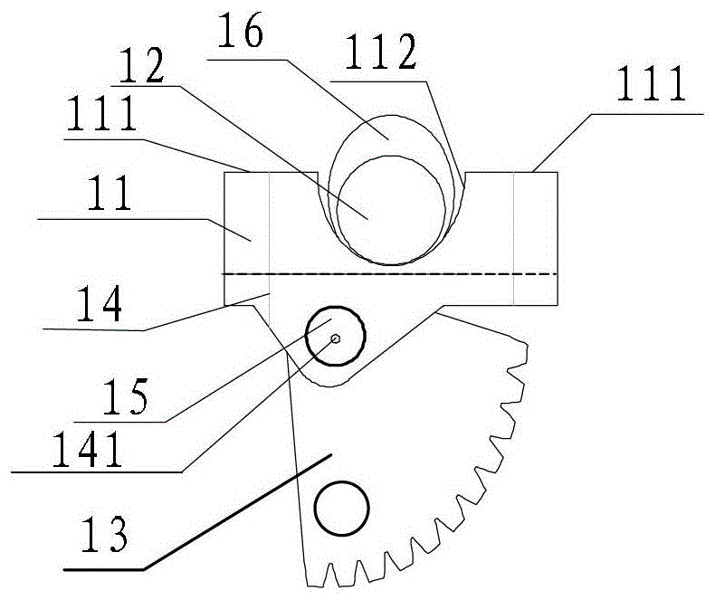
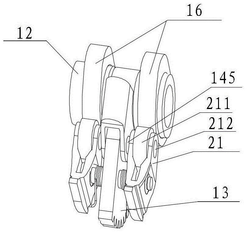
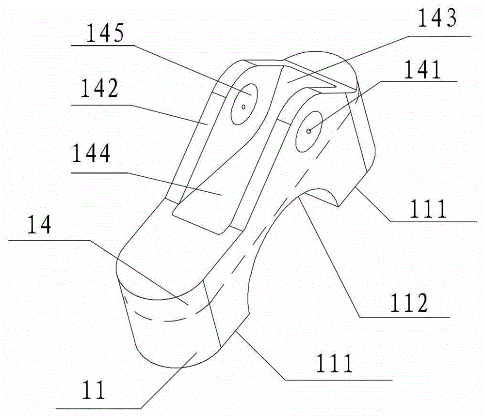
[0022] An embodiment of the present invention provides a cam bearing seat for a variable valve lift driving device, such as figure 1 As shown, it is arranged between the camshaft 12 and the driving part 13, including the supporting part 11, the connecting part 14 fixedly connected with the supporting part 11 and the adjustment center 141 arranged on the connecting part 14; the supporting part 11 is used to support the camshaft 12 ; the connecting part 14 is movably connected with the driving part 13 at the adjustment center 141 , so that the driving part 13 rotates around the adjustment center 141 .

[0023] The cam bearing seat used in the variable valve lift driving device provided by the embodiment of the present invention not only plays the role of supporting the camshaft ...


PUM


Abstract

The invention provides a cam bearing block applied to a continuous variable valve lift driving device and relates to engine parts, solving the problem that an engine is high in cost and poor in economical efficiency by using an existing cam bearing block. The cam bearing block applied to a continuous variable valve lift driving device provided by the invention is arranged between a cam shaft and a driving part, and comprises a supporting part, a connecting part fixedly connected with the supporting part and a regulating center arranged on the connecting part; the supporting part is used for supporting the cam shaft; the connecting part is movably connected with the driving part at the regulating center to enable the driving part to rotate around the regulating center.

Description

technical field [0001] The present invention relates to engine components, and more particularly to cam bearing housings for variable valve lift drives. Background technique [0002] An engine equipped with a variable valve lift driving device can change the valve lift according to different working conditions of the engine, thereby improving the efficiency of the engine and reducing fuel consumption. [0003] The variable valve lift driving device usually includes a valve, a valve connecting rod connected to the valve, a valve rocker arm connected to the valve connecting rod, and a camshaft that drives the valve to open or close. There is a swing between the camshaft and the valve rocker arm. The swing arm is connected with a driving part, which is used to drive the swing arm to realize the change of the valve lift. [0004] A camshaft is a shaft that houses one or more cams, supported by cam bearing housings. In the variable valve lift driving device, the cam bearing sea...

Claims


Application Information

Patent Timeline
Patent Type & Authority Patents(China)
IPC IPC(8): F01L1/047
Inventor 刘涛刘胜强林文马国海赵卫平
Owner GREAT WALL MOTOR CO LTD
Why Eureka
Try Eureka