A method and device for testing the bending and torsion mechanical properties of an h-shaped girder frame

A testing method and testing device technology, applied in the field of automobile manufacturing, can solve the problems of undisclosed parts and the like

Active Publication Date: 2016-08-24
BAOSHAN IRON & STEEL CO LTD
View PDF8 Cites 0 Cited by
  • Summary
  • Abstract
  • Description
  • Claims
  • Application Information

AI Technical Summary

Problems solved by technology

[0007] To sum up, the existing patents are mainly for testing single loads (bending or torsion) on relatively simple single parts (mainly shaft parts), but there is no disclosure of H-shaped girder frame parts

Method used


Image

  • A method and device for testing the bending and torsion mechanical properties of an h-shaped girder frame
  • A method and device for testing the bending and torsion mechanical properties of an h-shaped girder frame
  • A method and device for testing the bending and torsion mechanical properties of an h-shaped girder frame

Examples


Embodiment 1

[0060] Example 1: H-shaped girder frame-Q345 bending and torsion test

[0061] Using the test device to test the H-shaped girder frame-Q345 bending torsion test, under the load of 1KN, 2KN, 3KN, 4KN, 5KN, 6KN, 7KN, 8KN, 9KN, 10KN, the displacement changes of key parts, such as Figure 6 As shown, the strain changes in key parts, such as Figure 7 shown.

[0062] Figure 6 It shows that among the three directions, the Z-axis changes up to about 10mm, and the X-axis changes the least. Within 1mm, the maximum displacement of the Y-axis is less than 2mm.

[0063] Figure 7 It shows that the microstrain at the 10 strain test points changes linearly with the load, and the range of change is relatively small. The maximum tensile strain is 13με, and the maximum compressive strain is -19με.

Embodiment 2

[0064] Example 2: H-shaped girder frame-QSTE700 bending torsion test

[0065] Using the test device to test H-shaped girder frame-QSTE700 bending torsion test, under the action of 1KN, 1.5KN, 2KN, 2.5KN, 3KN, 3.5KN, 4KN, 4.5KN loading force, the displacement changes of key parts, such as Figure 8 As shown, the strain changes in key parts, such as Figure 9 shown.

[0066] Figure 8 It shows that the maximum change in Z axis is about 12mm, the change in X direction is the smallest, within 1mm, and the maximum displacement of Y axis is 2mm.

[0067] Figure 9 It shows that the microstrain at the 10 strain test points changes linearly with the load, the range of change is small, the maximum tensile strain is 24με, and the maximum compressive strain is -22με.

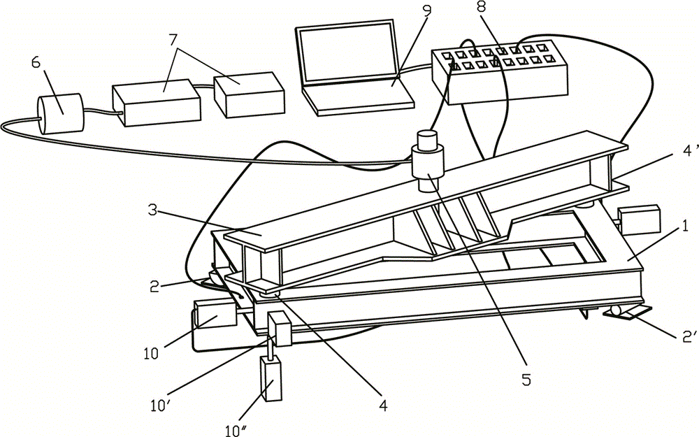
[0068] The method and device for testing the bending and torsion mechanical properties of the H-shaped girder frame by the present invention can be used to investigate the calculation of deformation, angle and displace...


PUM


Abstract

The invention discloses a method and device for testing bending torsion mechanics performance of an H-shaped girder framework. The method comprises the following steps that firstly, a test platform is constructed, the two ends of one opposite angle of the H-shaped girder framework are placed on two bottom supporting bases, loading beams are placed at the two ends of the other opposite angle, beam loading supports are arranged below the two ends of the loading beams, the centers of the loading beams are provided with a loading hydraulic cylinder connected with a power pump and a loading instrument, the outer side faces of the middle portions of H-shaped girders at the two ends of the H-shaped girder framework are respectively pasted with five strain gages which are electrically connected with a balanced bridge and a computer, and displacement meters are placed at the positions, corresponding to the X-axis direction, the Y-axis direction and the Z-axis direction, of the two loading angles of the H-shaped girder framework respectively and electrically connected with the balanced bridge; secondly, the bending torsion testing is prepared; thirdly, loading testing is carried out, loading is carried out at random within the material elasticity range, the displacement and strain of the measuring position are obtained through the computer, the power pump is controlled through the loading instrument to enable the load to reach a target load, testing is repeatedly carried out three times, and mechanics performance testing under different loads can be achieved in sequence.

Description

technical field [0001] The present invention relates to a method and a device in the technical field of automobile manufacturing, in particular to a method and a device for testing the bending and torsion mechanical properties of an H-shaped beam frame of an ultra-high-strength steel automobile frame, which can be used to examine whether the wheels of a truck are placed at diagonal angles during driving. The strain, displacement, torsion angle and load magnitude of the key parts caused by the combined bending and torsional load of the frame. Background technique [0002] The modern automotive industry has higher and higher requirements for lightweight, safety, exhaust emissions, cost control and fuel economy, which drives the automotive industry to adopt high-strength steel plates and some high-strength lightweight materials. The car frame is an important load-bearing part of the car. According to statistics, the mass of the car body accounts for about 40% to 60% of the car'...

Claims


Application Information

Patent Timeline
Patent Type & Authority Patents(China)
IPC IPC(8): G01M17/007
Inventor 罗爱辉刁可山徐伟力
Owner BAOSHAN IRON & STEEL CO LTD
Why Eureka
Try Eureka