Ground capacitance detection circuit for DC power system

A technology of DC power supply system and voltage detection circuit, which is applied in the field of circuits, can solve problems such as inaccurate measurement results, potential safety hazards of detection circuits, and influence on the operation of DC power supply systems, achieving wide application range, high detection accuracy, and high promotion and application value Effect

Active Publication Date: 2014-07-16
SHENZHEN GOLDEN HIGHWAY TECH CO LTD
View PDF6 Cites 4 Cited by
  • Summary
  • Abstract
  • Description
  • Claims
  • Application Information

AI Technical Summary

Problems solved by technology

[0009] In view of this, the embodiment of the present invention provides a DC power system ground capacitance detection circuit to solve the technical problems that the detection circuit in the prior art has potential safety hazards, inaccurate measurement results, and will affect the normal operation of the DC power system.

Method used


Image

  • Ground capacitance detection circuit for DC power system
  • Ground capacitance detection circuit for DC power system
  • Ground capacitance detection circuit for DC power system

Examples


Embodiment 1

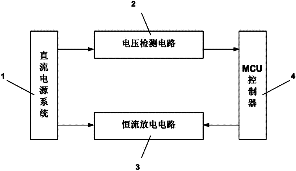
[0019] As shown in Figure 1, the present invention provides a DC power system ground capacitance detection circuit, the circuit includes: a voltage detection circuit (2) connected to the DC power system (1) for detecting the discharge voltage of the DC power system ground capacitance ); connected with the DC power supply system (1), a constant current discharge circuit (3) used to discharge the DC power supply system (1) to the ground capacitance; connected with the constant current discharge circuit (3) and the voltage detection circuit (2) , an MCU controller (4) used to control the constant current discharge circuit (3) to discharge the DC power supply system (1) to the ground capacitance and to time the timing.

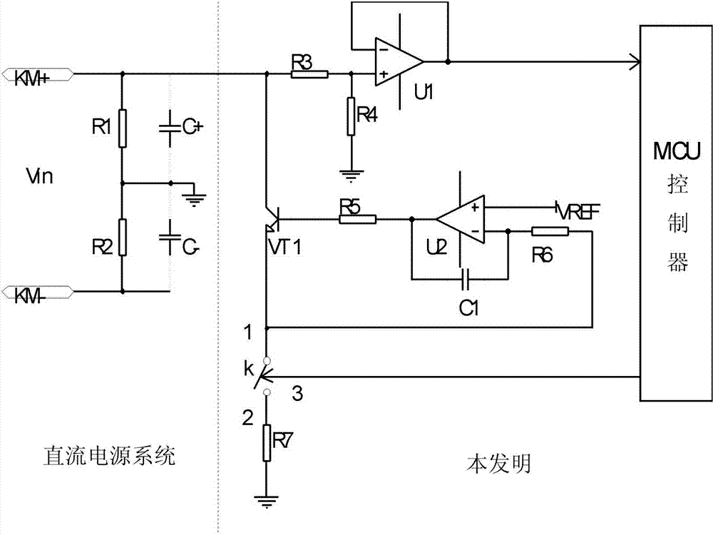
[0020] figure 2 It is the schematic circuit diagram of this embodiment. In the figure, the left side of the dotted line is the structural diagram of the DC power supply system (1), and the right side of the dotted line is the structural diagram of the ground capa...

Embodiment 2

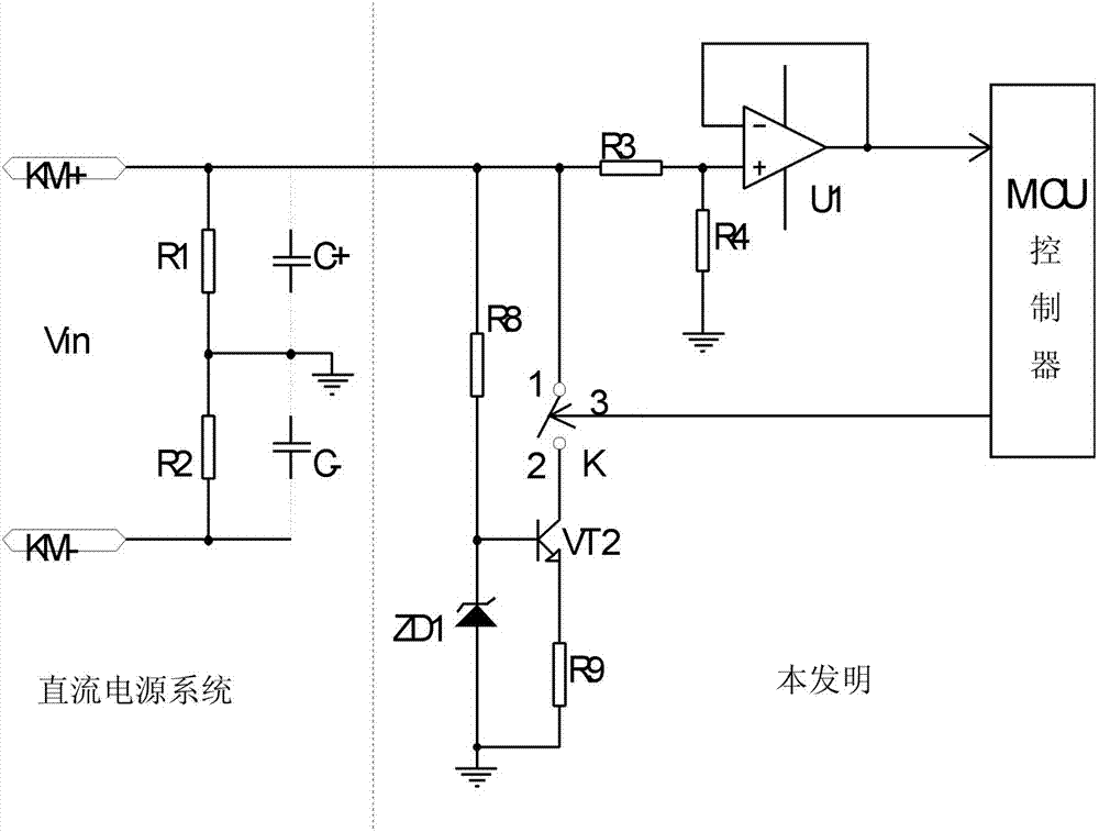
[0025] image 3 It is the schematic circuit diagram of this embodiment. In the figure, the left side of the dotted line is the structural diagram of the DC power supply system (1), and the right side of the dotted line is the structural diagram of the ground capacitance detection circuit of the DC power supply system according to the embodiment of the present invention.

[0026] to combine image 3 , The difference between this embodiment and Embodiment 1 is that the structure of the constant current discharge circuit (3) is different. In this embodiment, the constant current discharge circuit (3) includes: a switch K, an NPN transistor VT2, a voltage regulator tube ZD1, and resistors R8 and R9. One end of the resistor R8 is connected to the DC power system bus KM+, the other end of the resistor R8 is connected to the cathode of the voltage regulator tube ZD1, and the anode of the voltage regulator tube ZD1 is grounded; the first end "1" of the switch K is connected to the T...

Embodiment 3

[0028] Figure 4 It is the schematic circuit diagram of this embodiment. In the figure, the left side of the dotted line is the structural diagram of the DC power supply system (1), and the right side of the dotted line is the structural diagram of the ground capacitance detection circuit of the DC power supply system according to the embodiment of the present invention.

[0029] to combine Figure 4 The difference between this embodiment and the first embodiment is that the structure of the constant current discharge circuit (3) is different. In this embodiment, the constant current discharge circuit (3) includes: a switch K, NPN transistors VT3, TL431, and resistors R10 and R11. One end of the resistor R10 is connected to the DC power system bus KM+, and the other end of the resistor R10 is connected to the C pole of the TL431; the first end "1" of the switch K is connected to the DC power system bus KM+, and the switch K's The second terminal "2" is connected to the colle...


PUM


Abstract

The invention discloses a ground capacitance detection circuit for a DC power system. The ground capacitance detection circuit comprises a voltage detection circuit connected with the DC power system and used for detecting DC power system ground capacitance discharge voltage, a constant current discharge circuit connected with the DC power system and used for enabling the DC power system ground capacitance to discharge, and a MCU controller connected with the constant current discharge circuit and the voltage detection circuit and used for timing and for controlling the constant current discharge circuit for enabling the DC power system ground capacitance to discharge. The ground capacitance detection circuit for the DC power system is simple in circuit structure, novel and reasonable in design, and high in detection precision, and can on-line detect the ground capacitance of the DC power system in real-time under a condition that normal operation of the DC power system is not affected.

Description

technical field [0001] The invention relates to the field of circuit technology, in particular to a ground capacitance detection circuit of a DC power supply system. Background technique [0002] The insulation monitoring device is a device for online real-time detection and management of the insulation status of the DC power system bus and branches. It has been widely used in various specifications of power operating power systems, solar photovoltaic grid-connected systems, and DC remote power supplies. System, HVDC high voltage direct current power supply system insulation state detection and management. [0003] The generation of capacitance to ground of DC power supply system is unique to DC power supply system and cannot be avoided. The generation of capacitance to ground mainly comes from the following three aspects: one is the distributed capacitance of cable to ground, but the value of distributed capacitance of general cable to ground Relatively small, it is not th...

Claims


Application Information

Patent Timeline
Patent Type & Authority Applications(China)
IPC IPC(8): G01R27/26
Inventor 刘树林翦志强武虎雄
Owner SHENZHEN GOLDEN HIGHWAY TECH CO LTD
Why Eureka
Try Eureka