A DC power system ground capacitance detection circuit
A technology for a DC power supply system and a voltage detection circuit, applied in the field of circuits, can solve the problems of inaccurate measurement results, hidden dangers of detection circuit safety, affecting the operation of the DC power supply system, etc., achieving a wide range of applications, high detection accuracy, and high promotion and application value. Effect
- Summary
- Abstract
- Description
- Claims
- Application Information
AI Technical Summary
Problems solved by technology
Method used
Image
Examples
Embodiment 1
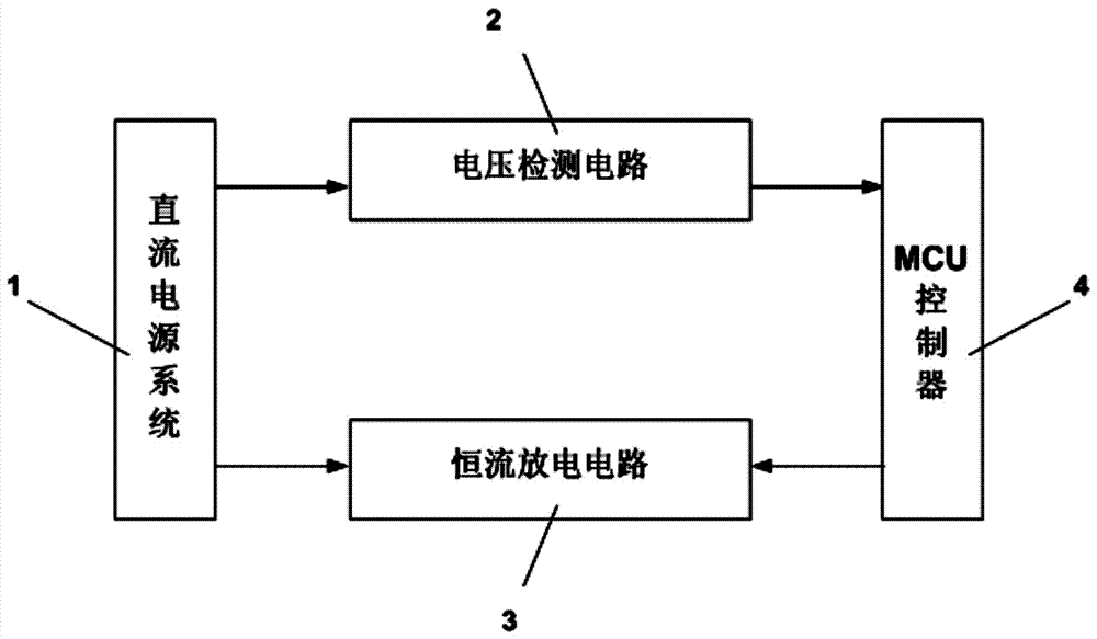
[0018] As shown in Figure 1, the present invention provides a DC power system ground capacitance detection circuit, the circuit includes: a voltage detection circuit (2) connected to the DC power system (1) for detecting the discharge voltage of the DC power system ground capacitance ); connected with the DC power supply system (1), a constant current discharge circuit (3) used to discharge the DC power supply system (1) to the ground capacitance; connected with the constant current discharge circuit (3) and the voltage detection circuit (2) , an MCU controller (4) used to control the constant current discharge circuit (3) to discharge the DC power supply system (1) to the ground capacitance and to time the timing.
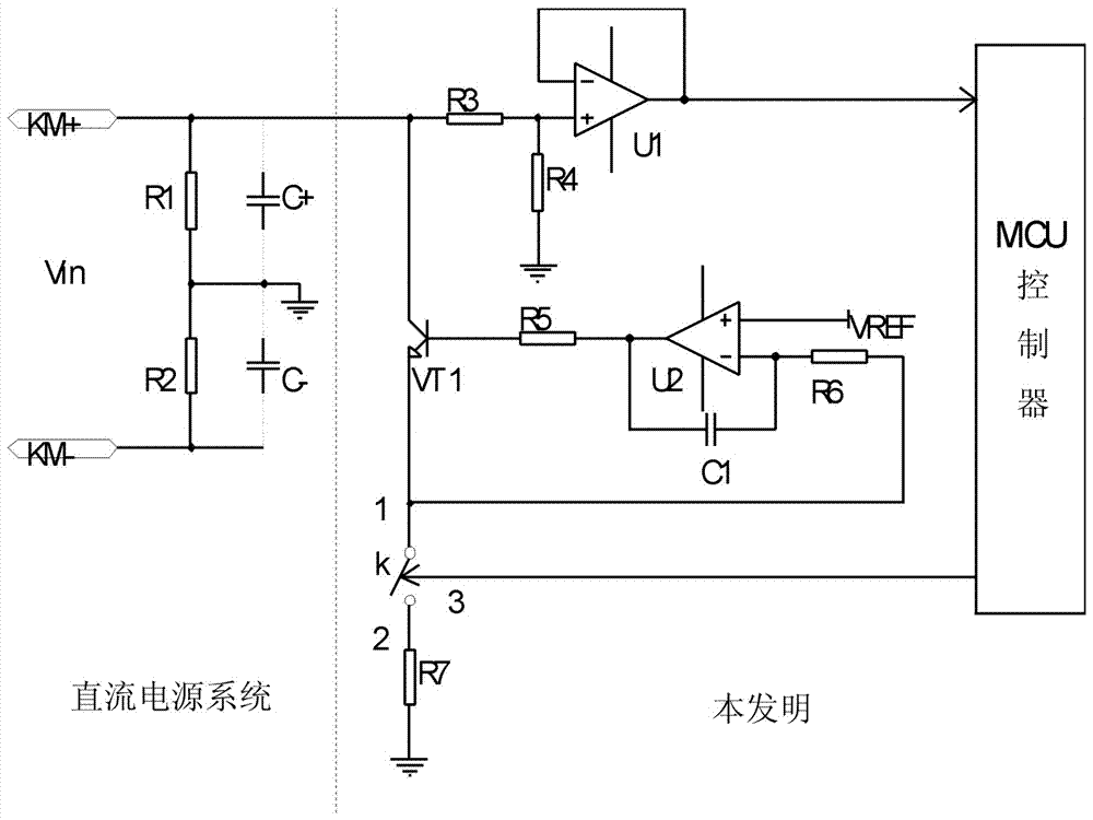
[0019] figure 2 It is the schematic circuit diagram of this embodiment. In the figure, the left side of the dotted line is the structural diagram of the DC power supply system (1), and the right side of the dotted line is the structural diagram of the ground capa...
Embodiment 2
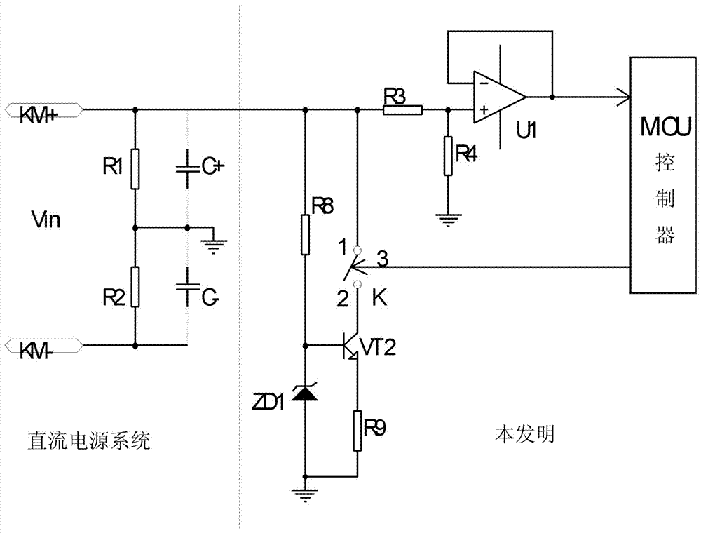
[0024] image 3 It is the schematic circuit diagram of this embodiment. In the figure, the left side of the dotted line is the structural diagram of the DC power supply system (1), and the right side of the dotted line is the structural diagram of the ground capacitance detection circuit of the DC power supply system according to the embodiment of the present invention.
[0025] combine image 3 , The difference between this embodiment and Embodiment 1 is that the structure of the constant current discharge circuit (3) is different. In this embodiment, the constant current discharge circuit (3) includes: a switch K, an NPN transistor VT2, a voltage regulator tube ZD1, and resistors R8 and R9. One end of the resistor R8 is connected to the DC power system bus KM+, the other end of the resistor R8 is connected to the cathode of the voltage regulator tube ZD1, and the anode of the voltage regulator tube ZD1 is grounded; the first end "1" of the switch K is connected to the The ...
Embodiment 3
[0027] Figure 4 It is the schematic circuit diagram of this embodiment. In the figure, the left side of the dotted line is the structural diagram of the DC power supply system (1), and the right side of the dotted line is the structural diagram of the ground capacitance detection circuit of the DC power supply system according to the embodiment of the present invention.
[0028] combine Figure 4 The difference between this embodiment and the first embodiment is that the structure of the constant current discharge circuit (3) is different. In this embodiment, the constant current discharge circuit (3) includes: a switch K, NPN transistors VT3, TL431, and resistors R10 and R11. One end of the resistor R10 is connected to the DC power system bus KM+, and the other end of the resistor R10 is connected to the C pole of the TL431; the first end "1" of the switch K is connected to the DC power system bus KM+, and the switch K's The second terminal "2" is connected to the collecto...
PUM
 Abstract
Description
Claims
Application Information
 - R&D
- Intellectual Property
- Life Sciences
- Materials
- Tech Scout
- Unparalleled Data Quality
- Higher Quality Content
- 60% Fewer Hallucinations
Browse by: Latest US Patents, China's latest patents, Technical Efficacy Thesaurus, Application Domain, Technology Topic, Popular Technical Reports.
© 2025 PatSnap. All rights reserved.Legal|Privacy policy|Modern Slavery Act Transparency Statement|Sitemap|About US| Contact US: help@patsnap.com


