Micro-power-consumption M-bus slave end circuit for intelligent instrument communication and communication method thereof

A smart instrument, micro-power consumption technology, applied in the direction of instruments, computer control, general control systems, etc., can solve the problems of slow communication speed, poor circuit stability of simple discrete components, complex peripheral devices, etc., to reduce power consumption and communication speed unaffected effect

Inactive Publication Date: 2014-07-16
TIANJIN BINGHUA ENERGY TECH
View PDF6 Cites 8 Cited by
  • Summary
  • Abstract
  • Description
  • Claims
  • Application Information

AI Technical Summary

Problems solved by technology

[0005] Aiming at the structural deficiencies in the prior art, the purpose of the present invention is to provide a micro-power consumption M-bus slave terminal circuit and its communication method for intelligent instrument communication, so as to solve the problem of high cost of application-specific integrated circuits and peripheral devices. Complicated and simple discrete components have poor circuit stability, low communication reliability, and slow communication speed.

Method used


Image

  • Micro-power-consumption M-bus slave end circuit for intelligent instrument communication and communication method thereof
  • Micro-power-consumption M-bus slave end circuit for intelligent instrument communication and communication method thereof

Examples


Embodiment 1

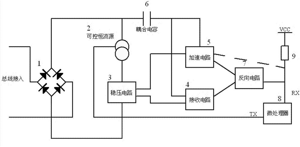
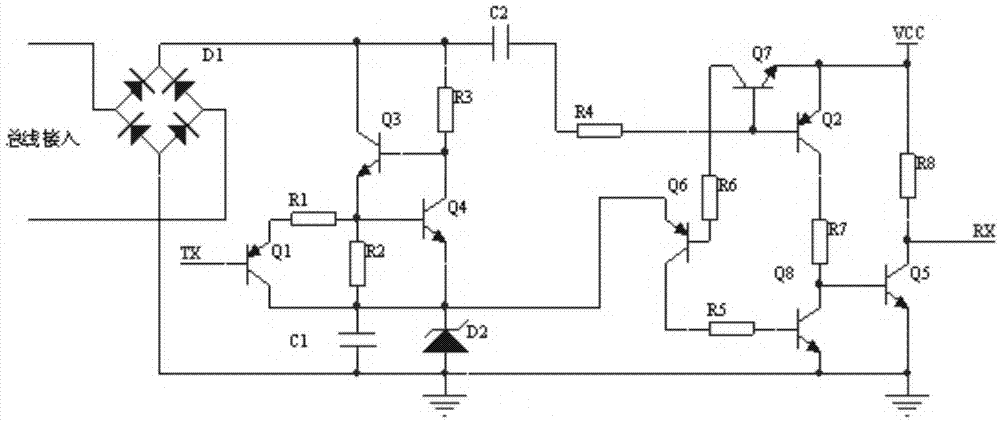
[0018] Such as figure 1 , 2 shown, corresponding to figure 2 In the embodiment circuit, the controllable constant current source 2 circuit is composed of triode Q1, triode Q3, triode Q4, resistor R2, and resistor R3, wherein the constant current source circuit is composed of triode Q3, triode Q4, resistor R2, and resistor R3. R1 and transistor Q1 are constant current source control circuits. Capacitor C1 , voltage regulator tube D2 and the controllable constant current source circuit constitute a voltage regulator circuit 3 , and capacitor C2 and resistor R4 constitute a coupling circuit 6 . Transistor Q2 and resistor R7 form receiving circuit 4, triode Q6, triode Q7, triode Q8, resistor R5 and resistor R6 form acceleration circuit 5, triode Q5 and resistor R8 form reverse circuit 7.

Embodiment 2

[0020] On the basis of the circuit in Embodiment 1, the data communication method provides a stable initial voltage on the bus. When there is data, a falling edge appears on the bus, the voltage decreases, and the receiving circuit 4 receives the signal from high to low. A high potential is output from the transistor Q2, which is passed through the resistor R7 to the reverse circuit 7, and then output to the low level of RX after inversion; when the bus returns to the initial voltage and the voltage rises, there will be a rising edge signal from low to high, and the receiving In the circuit, the transistor Q2 is turned off, the receiving circuit 4 is turned off, the transistor Q7 in the acceleration circuit 5 is turned on, the transistor Q6 is turned on, and the transistor Q8 is turned on, so that the accelerated transistor Q5 is cut off, and RX outputs a high level. This completes the physical circuit for the entire process of receiving data. The sending circuit is composed o...


PUM


Abstract

The invention provides a micro-power-consumption M-bus slave end circuit for intelligent instrument communication. The circuit is connected with an M-bus, a rectifier bridge circuit of the circuit is connected with an inlet line of the M-bus, the negative end of the rectifier bridge circuit is grounded, the positive end of the rectifier bridge circuit is connected with the positive end of a controllable constant current source circuit, the control end of the controllable constant current source circuit is connected with a microprocessor TX, the negative end of the controllable constant current source circuit is connected with the input of a voltage stabilizing circuit, the output of the voltage stabilizing circuit is connected with a receiving circuit and provides a reference potential for the receiving circuit and an accelerating circuit, a coupling receiving circuit and the accelerating circuit are connected to the positive end of the rectifier bridge circuit through a coupling capacitor, the coupling receiving circuit and the output end of the acceleration circuit are connected with the input end of a reverse circuit, the output end of the reverse circuit is connected with the RX end of the microprocessor, and the RX end is connected with a power source of a controller through a resistor. Meanwhile, a communication method used for the micro-power-consumption M-bus slave end circuit for the intelligent instrument communication is adopted. The micro-power-consumption M-bus slave end circuit and the communication method have the advantages that after the circuit is applied, the steady-state current can be smaller than 50 microamperes and smaller than the standard steady-state current by 30 times, and the communication Baud rate can reach 9600.

Description

technical field [0001] The present invention relates to a micro-power consumption M-bus slave terminal circuit for intelligent instrument communication, especially for data acquisition systems of water meters, gas meters, heat meters and other related metering equipment and instruments. Slave devices connected to the host, and micro-power M-bus circuits in instruments. Background technique [0002] M-Bus, proposed by Paderborn University, is a data bus designed specifically for the transmission of information from consumption measuring instruments and counters. M-Bus has many applications in building and industrial energy consumption data collection. [0003] According to the electrical definition of the M-bus bus standard EN1434-3, the signal transmitted from the host end to the slave end is expressed by the change of the voltage value, that is, the signal sent from the host end to the slave end is a voltage pulse sequence with + 36V represents a logic "1", and +24V repre...

Claims


Application Information

Patent Timeline
Patent Type & Authority Applications(China)
IPC IPC(8): G05B19/042
Inventor 张炳华张洋
Owner TIANJIN BINGHUA ENERGY TECH
Why Eureka
Try Eureka