
Combined electric probe and processing method for high-speed moving metal flyer test

A metal flyer and processing method technology, which is applied to devices for measuring time intervals, electrical unknown time interval measurement, instruments, etc. problems such as R&D costs and experimental costs, to achieve the effect of reducing research costs, shortening research cycles, and reducing the spray range

Active Publication Date: 2016-03-30
SICHUAN HUAFENG ENTERPRISE GRP
View PDF2 Cites 0 Cited by
  • Summary
  • Abstract
  • Description
  • Claims
  • Application Information

AI Technical Summary

Problems solved by technology

The use of the original electrical probes will bring two adverse consequences: one is that due to the larger diameter of the probes, denser electrical probes cannot be arranged under the flyer, but due to the particularity of the warhead design, the The flyer driven by the boom will have a large deformation during the movement process, and the probes with too large spacing cannot fully reflect the deformation of the flyer; second, the design of the warhead needs to understand the behavior of a certain position on the flyer. The interference between the needles is serious, and it is impossible to bundle a single probe together for use, so it is impossible to continuously measure the continuous motion behavior of a certain position on the flyer. Multiple detonation experiments are necessary to obtain the data of the continuous motion of the flyer. Increased research and development costs and experimental costs

Method used


Image

  • Combined electric probe and processing method for high-speed moving metal flyer test
  • Combined electric probe and processing method for high-speed moving metal flyer test
  • Combined electric probe and processing method for high-speed moving metal flyer test

Examples


Embodiment Construction

[0046] The present invention will be further described below in conjunction with accompanying drawing:

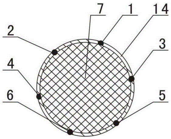
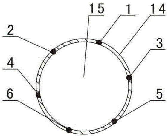
[0047] Such as figure 1 , figure 2 and image 3 Shown, the combined electric probe that is used for the high-speed motion metal flyer test of the present invention comprises film cylinder 14, solid glass cylinder 7 and a plurality of wires, and the quantity of metal wire is determined by the diameter of film cylinder 14 and the distance between the adjacent metal wires. In this example, there are six metal wires, which are the first metal wire 1, the second metal wire 2, the third metal wire 3, the fourth metal wire 4, and the fifth metal wire 5. , the sixth metal wire 6, the adhesive film cylinder 14 is a circular cylinder made of adhesive film, and a plurality of metal wires are evenly distributed on the circumferential wall of the adhesive film cylinder 14 and covered by the adhesive film of the adhesive film cylinder 14 Coating, the metal wire is coaxial with the ad...


PUM


Abstract

The invention discloses a combined type electric probe for testing a high-speed moved metal flyer. Multiple metal wires are distributed on the circumferential wall of an adhesive-film cylinder evenly, the front ends of different mental wires are not aligned and form multiple steps together with the front end of an adhesive film, a fixing cylinder is located on the rear section inside the adhesive-film cylinder and is connected with the adhesive-film cylinder mutually, the front end of the fixing cylinder is more closer to the rear end of the adhesive-film cylinder than the front ends of all the metal wires. The invention further discloses a machining method of the combined type electric probe. The method comprises the steps of manufacturing an adhesive-film plate with the mental wires, carrying pressing and solidification, carrying out and a step cutting and finishing, carrying out leading wire numbering, manufacturing a fixing upright, manufacturing the adhesive-film cylinder with the metal wires, bonding and solidifying the fixing upright and obtaining the finished combined type electric probe after checking and packaging. The combined type electric probe is adopted for experiment, experiment data which can only be obtained through multiple times of experiments traditional can be obtained in one time experiment, research cost is lowered obviously, and research period is shortened.

Description

technical field [0001] The invention relates to an electric probe and a processing method in the field of sensors for shock wave physics and detonation physics testing, a combined electric probe and a processing method for testing high-speed moving metal flyers. Background technique [0002] In the field of basic research such as the detonation performance of explosives and the high-pressure physical properties of materials under shock compression, the motion state of flyers is the basic measurement object to characterize the working ability of explosives and the high-pressure physical properties of metal materials; during the development of warheads , the detonation work of explosives to drive the movement of metal flyers is an important feature that characterizes product design performance, reflecting the product's killing effect, armor-piercing ability, and convergence compression degree. Evidence on whether the performance of the product deteriorates after long-term stor...

Claims


Application Information

Patent Timeline
Patent Type & Authority Patents(China)
IPC IPC(8): H01R13/24G04F10/00
Inventor 丁利华谷岩王小龙王军赵川梅汤海泓陈立云李军张从和
Owner SICHUAN HUAFENG ENTERPRISE GRP
Learn More