Gate drive circuit, power switching circuit and gate drive method

A gate drive circuit and gate drive technology, applied in electronic switches, electrical components, pulse technology, etc., can solve problems such as breakdown, and achieve the effect of ensuring normal switch switching

Active Publication Date: 2014-07-16
HANGZHOU SILAN MICROELECTRONICS
View PDF5 Cites 5 Cited by
  • Summary
  • Abstract
  • Description
  • Claims
  • Application Information

AI Technical Summary

Problems solved by technology

LDMOS transistors are prone to high gat

Method used


Image

  • Gate drive circuit, power switching circuit and gate drive method
  • Gate drive circuit, power switching circuit and gate drive method
  • Gate drive circuit, power switching circuit and gate drive method

Examples


Embodiment Construction

[0033]Various embodiments of the invention will be described in more detail below with reference to the accompanying drawings. In the various drawings, the same elements are denoted by the same or similar reference numerals. For the sake of clarity, various parts in the drawings have not been drawn to scale.

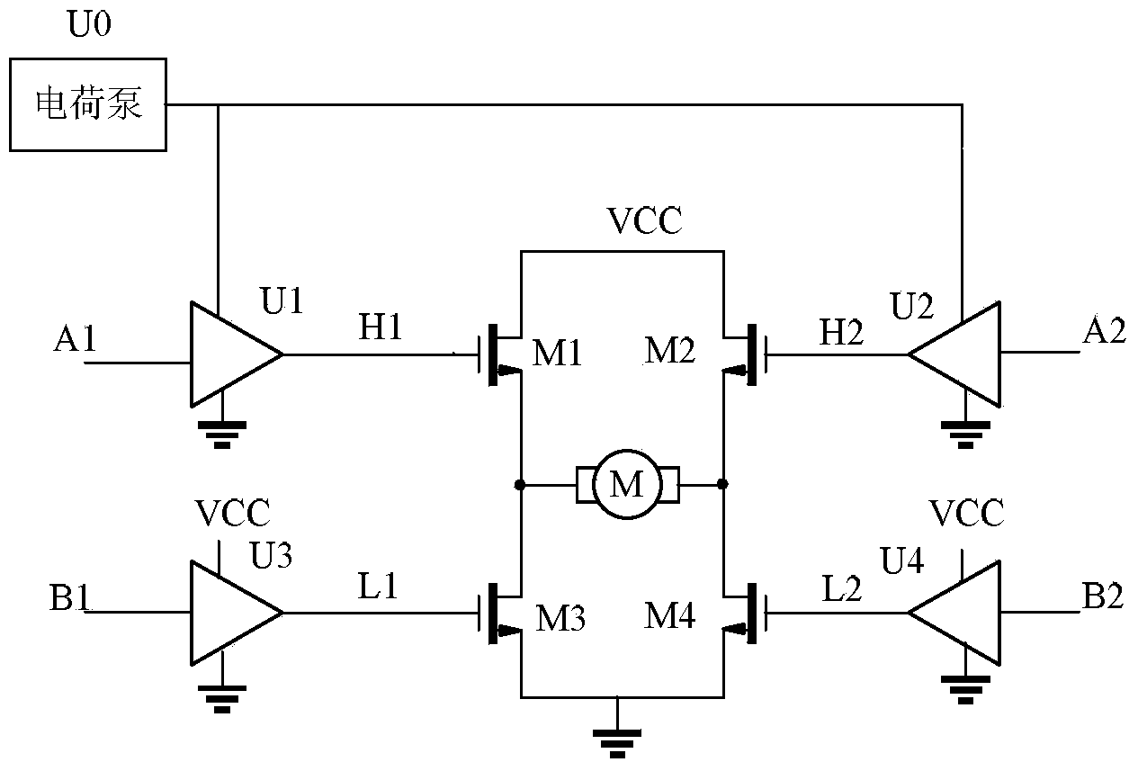
[0034] figure 1 is a schematic circuit diagram of a power switching circuit according to the prior art. In prior art configurations, the power switching circuit may include two LDMOS transistors arranged in a half H-bridge, or four LDMOS transistors arranged in a full H-bridge, for driving a load.

[0035] exist figure 1 In the power switch circuit shown, four LDMOS transistors M1-M4 are shown in a full H-bridge configuration. The first group of two LDMOS transistors M1 and M3 are connected in series between the power supply VCC and the ground GND, and the second group of two LDMOS transistors M2 and M4 are connected in series between the power supply VCC and the gro...


PUM


Abstract

The invention discloses a gate drive circuit, a power switching circuit and a gate drive method. The gate drive circuit comprises a power supply end, a grounded end, an input end and an output end, wherein the gate drive circuit receives gate drive input signals at the input end, and provides gate drive output signals at the output end to drive a semi-conductor switch, the gate drive circuit further comprises a clamping end, the gate drive circuit keeps a voltage difference between the output end and the clamping end at a first constant value when the gate drive input signals are first levels, and the gate drive circuit keeps the voltage difference between the output end and the clamping end at a second constant value when the gate drive input signals are second levels. The gate drive circuit can keep a gate source voltage of the semi-conductor switch at a constant voltage difference, and it is avoided that the gate source voltage changes because of influence of loads. The gate drive circuit can prevent the situation that the semi-conductor switch is broken through because of the high gate source voltage.

Description

technical field [0001] The present invention relates to a power switch circuit, in particular to a gate drive circuit for a semiconductor switch device, a power switch circuit including the gate drive circuit and a gate drive method. Background technique [0002] A power switching circuit for driving a motor includes semiconductor switching devices such as metal oxide semiconductor field effect transistors (MOSFETs) and insulated gate bipolar transistors (IGBTs) and the like. In a power switching circuit, the high-side semiconductor switching device connected to the power supply terminal sometimes needs to withstand a high voltage exceeding 600V. A laterally diffused metal-oxide-semiconductor field-effect transistor (LDMOS transistor) includes source and drain regions implanted twice in the same area and formed by a high-temperature drive-in process. In LDMOS transistors, the source and drain regions are diffused laterally under the gate, forming a channel with a concentrat...

Claims


Application Information

Patent Timeline
IPC IPC(8): H03K17/567
Inventor 郑烷胡铁刚
Owner HANGZHOU SILAN MICROELECTRONICS
Why Eureka
Try Eureka