Radio frequency switching device for model approval DFS test
A technology of switching devices and models, applied in transmission monitoring, electrical components, wireless communication, etc., can solve the problems that affect the accuracy of test results, increase the workload of testing, poor link stability, etc., and save time and effort in link construction. , improve the accuracy and efficiency, the effect of link attenuation controllable
- Summary
- Abstract
- Description
- Claims
- Application Information
AI Technical Summary
Problems solved by technology
Method used
Image
Examples
Embodiment 1
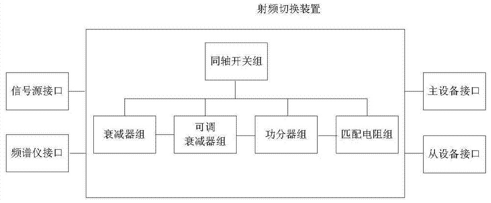
[0038] This embodiment provides a radio frequency link switching device used for type approval DFS testing, the structural diagram of the device is shown in the attached figure 1 As shown, it includes: multiple coaxial switches, multiple attenuators, multiple adjustable attenuators, multiple power dividers, and multiple impedance matching resistors.
[0039] A plurality of coaxial switches can be respectively connected to a group of attenuators, a group of adjustable attenuators, a group of power dividers, and a group of impedance matching resistors. When conducting type approval DFS tests, according to different test requirements, switch and select different attenuators, adjustable attenuators, power dividers, and matching resistors through coaxial switches. After switching in this way, different radio frequency links are formed due to different switching of the coaxial switch for different requirements.
[0040] The radio frequency link switching device can be connected wit...
Embodiment 2
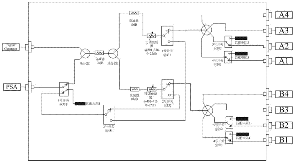
[0055] This embodiment provides a radio frequency link switching device for type approval DFS testing, and its specific schematic diagram is shown in the appendix figure 2 As shown, it includes: multiple coaxial switches, multiple attenuators, multiple adjustable attenuators, multiple power dividers, and multiple impedance matching resistors.
[0056] In this embodiment, the radio frequency link switching device is provided with A1-A4SMA interface, which is used to connect the master device, and the antenna radio frequency ports of the master device are connected sequentially, and the unconnected SMA ports are connected to the matching resistor through the coaxial switch, as figure 2 As shown in , the coaxial switch is No. 4 switch and No. 5 switch. These four antenna RF ports (when not connected, they are matching resistors, as shown in the figure, matching resistor 2 and matching resistor 3) are all connected to a power divider, and the output of the power divider is anoth...
PUM
 Abstract
Description
Claims
Application Information
 - R&D
- Intellectual Property
- Life Sciences
- Materials
- Tech Scout
- Unparalleled Data Quality
- Higher Quality Content
- 60% Fewer Hallucinations
Browse by: Latest US Patents, China's latest patents, Technical Efficacy Thesaurus, Application Domain, Technology Topic, Popular Technical Reports.
© 2025 PatSnap. All rights reserved.Legal|Privacy policy|Modern Slavery Act Transparency Statement|Sitemap|About US| Contact US: help@patsnap.com


