Grading jaw crusher and toothed plate thereof

A jaw crusher and tooth plate technology, which is applied in the field of mining machinery, can solve the problems that the jaw crusher does not adapt to new process requirements, and achieve the effect of reducing maintenance costs and reducing oil inlet and outlet pipelines

Active Publication Date: 2014-07-23
海门兴虹环保科技有限公司
View PDF4 Cites 2 Cited by
  • Summary
  • Abstract
  • Description
  • Claims
  • Application Information

AI Technical Summary

Problems solved by technology

[0003] The technical problem to be solved by the present invention: Aiming at the problem that the existing jaw crusher does not

Method used


Image

  • Grading jaw crusher and toothed plate thereof
  • Grading jaw crusher and toothed plate thereof

Examples


Embodiment 1

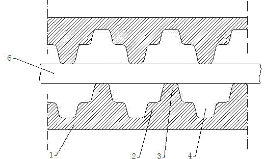
[0019] Example 1: The structure of the tooth plate used in this grading jaw crusher is as follows figure 1 As shown, there are alternate tines 3 and grooves 4 on the tooth plate 1 , so that three steps with different heights are formed on the entire tooth plate 1 . The distance between two adjacent tines 3 is 160 mm, the tooth height is 50 mm, the depth of the groove 4 is 30 mm, and the width is about 50 mm. The sides of the tines 3 and the groove 4 are inclined surfaces. Such as figure 1 As shown, the test plank 6 is placed between the two tooth plates 1. Since the tooth spacing is much larger than that of the original corrugated tooth plates, the test plank 6 can be broken with only a small force. Through experiments, it takes about 800N force to break a 9mm thick, 200mm long, and 16mm wide bar-shaped plank with the common tooth plate of 69 jaw crushers, but it only needs about 300N with the tooth plate of the present invention.

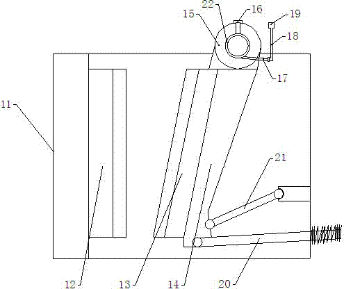
[0020] Both the fixed tooth plate 12 and...


PUM


Abstract

The invention discloses a jaw crusher toothed plate, which comprises a toothed plate (1) and teeth tines (3), and the space between the teeth tines is 3-5 times of the tooth height. A groove (4) is arranged between two adjacent teeth tines (3). After the teeth space between the teeth tines on the toothed plate is increased, the middle part of a stone material is suspended in midair between two teeth, and torque is increased, so that the stone material is easy to break, the production efficiency is improved, and the electric energy is saved.

Description

technical field [0001] The invention relates to a mining machine, in particular to a jaw crusher and its tooth plate structure. Background technique [0002] Since the birth of the jaw crusher, it has been responsible for the task of first breaking and second breaking. The diameter of the crushed stone is required to be less than 70mm, so the tooth spacing is generally 50~70mm, and the tooth section of the tooth plate is wavy. With the emergence of secondary crushing machines such as impact crushers, jaw crushers are only used as primary crushers, and the diameter of crushed stones can be appropriately relaxed. If the existing tooth plates continue to be used, there will be unnecessary energy consumption. The stone is squeezed and crushed by two alternating tooth plates in the jaw crusher, and the size of the tooth spacing directly affects the moment of force on the stone. Contents of the invention [0003] The technical problem to be solved by the present invention is t...

Claims


Application Information

Patent Timeline
IPC IPC(8): B02C1/02
Inventor 王福贵
Owner 海门兴虹环保科技有限公司
Why Eureka
Try Eureka