
A welding jig for the lower mounting bracket assembly in the middle of the ip body

A technology for installing brackets and welding fixtures, which is applied to welding equipment, auxiliary welding equipment, welding/cutting auxiliary equipment, etc. High efficiency, reasonable structure design, saving operation time

Active Publication Date: 2016-06-08
ANHUI DACHANG TECH
View PDF1 Cites 0 Cited by
  • Summary
  • Abstract
  • Description
  • Claims
  • Application Information

AI Technical Summary

Problems solved by technology

However, the structure of the instrument panel bracket applicable to this application is fixed, and the applicable surface is relatively single. It cannot adjust its own positioning size for different types of parts, and does not have the function of fine-tuning. Once the instrument panel bracket is produced, there will be certain processing. Or when there is an installation error, the fixture cannot be used to position and clamp the instrument panel bracket, and the instrument panel bracket needs to be repaired, which takes a long time, or the fixture is removed and re-drilled for installation to adjust the position of the fixture. production efficiency

Method used


Image

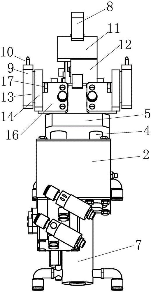
  • A welding jig for the lower mounting bracket assembly in the middle of the ip body
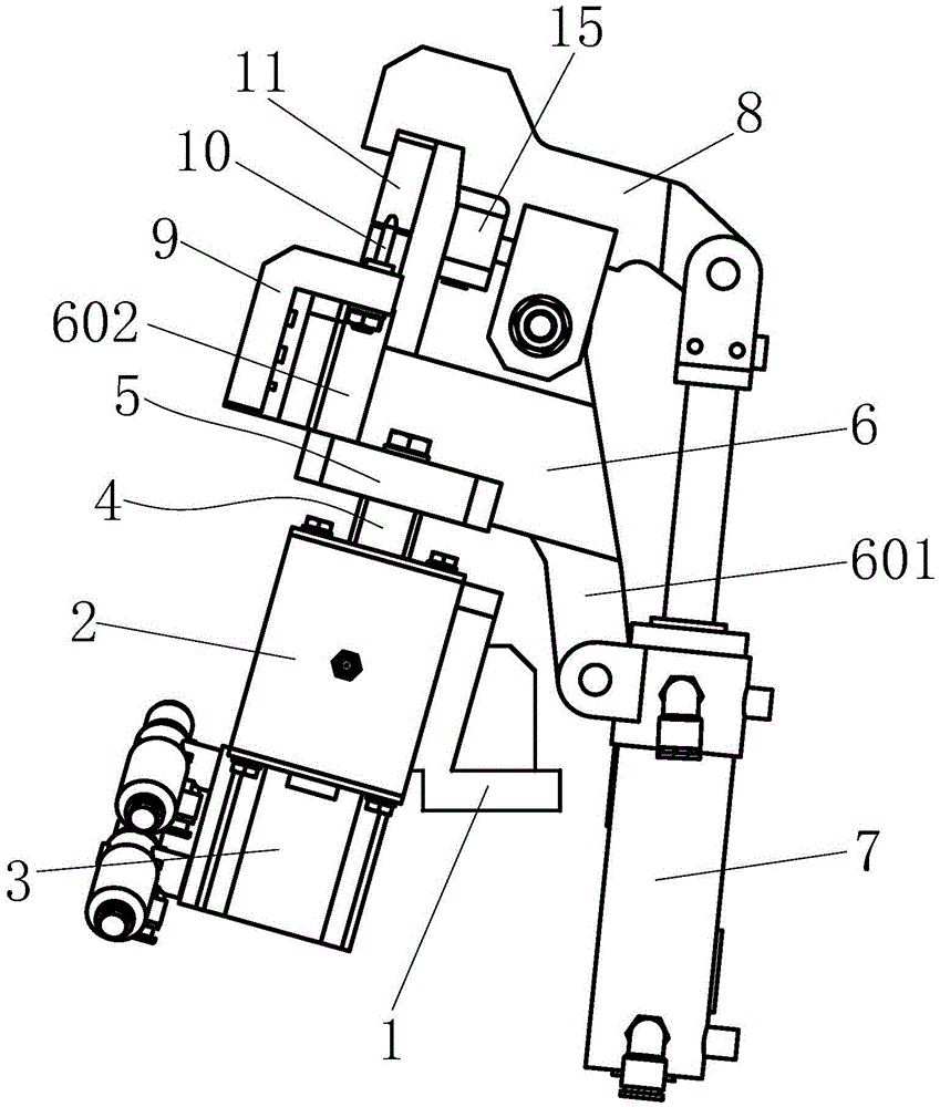
  • A welding jig for the lower mounting bracket assembly in the middle of the ip body
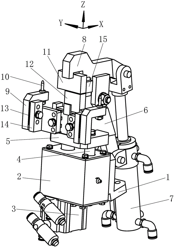
  • A welding jig for the lower mounting bracket assembly in the middle of the ip body

Examples


Embodiment Construction

[0020] In order to make the technical means, creative features, goals and effects achieved by the present invention easy to understand, the present invention will be further elaborated below.

[0021] like Figure 1 to Figure 7 As shown, a welding fixture for the lower mounting bracket assembly in the middle of the IP body includes a small corner seat 1, the angle between the upper side of the small corner seat 1 and the horizontal plane is an acute angle, and the angle is 74°. The small corner seat 1 An oblique fixed frame 2 is fixed on the upper side of the oblique fixed frame 2, and a driving guide device is fixedly installed on the oblique fixed frame 2. A side riser 6 is connected above the drive guide device, and a front connecting plate is provided at the front end of the side riser 6. 602, the front side of the front connecting plate 602 is symmetrically connected with a two-degree-of-freedom hole-fixing and distance-adjusting device, and the rear end of the side verti...


PUM


Abstract

The invention relates to a welding jig for an IP body lower middle installation support assembly. The welding jig comprises a small angle seat, wherein the included angle between the upper lateral side of the small angle seat and the horizontal plane is an acute angle, an oblique fixing frame is fixed on the upper lateral side of the small angle seat, a driving and guiding device is fixedly installed on the oblique fixing frame, a lateral vertical plate is connected to the upper side of the driving and guiding device, a front connecting plate is arranged at the front end of the lateral vertical plate, two-freedom-degree hole setting distance adjustment devices are symmetrically connected to the front side of the front connecting plate, and a clamping device is connected to the rear end of the lateral vertical plate. The welding jig has the advantages of being reasonable in structural design, convenient to operate and control, high in positioning and clamping efficiency and the like. By the adoption of the welding jig, automatic clamping and positioning are realized, the location dimension can be adjusted according to the type and size of a part of the IP body lower middle installation support assembly, the defect of an existing welding jig for the IP body lower middle installation support assembly that adjustability is poor is overcome, operation time is saved, and positioning and clamping efficiency is improved.

Description

technical field [0001] The invention relates to the technical field of auto parts processing, in particular to a welding jig for an IP body middle lower mounting bracket assembly. Background technique [0002] Due to the complex structure and many parts of the automobile instrument panel crossbeam, they are all produced by welding. For the components on the crossbeam of the automobile instrument panel, such as the lower mounting bracket assembly of the IP body, the welding positioning and clamping fixtures are mostly manually controlled, the degree of automation and clamping efficiency is low, and it is impossible to install the bracket assembly according to the middle of the IP body. The size change of the parts realizes the adjustment of its own size, and the applicable surface is narrow. Usually, when the type and size of the lower mounting bracket assembly of the IP body change, it is necessary to replace the entire set of welding fixtures for the lower mounting bracket ...

Claims


Application Information

Patent Timeline
Patent Type & Authority Patents(China)
IPC IPC(8): B23K37/04
CPCB23K37/0435
Inventor 陈新丁铭王鑫秋
Owner ANHUI DACHANG TECH
Learn More