Bionic four-foot robot provided with spinal joint and elastic legs

A quadruped robot and elastic leg technology, applied in the field of bionic robots, can solve the problems of not considering the deformation of system components, complex dynamic shape, unable to well reflect animal motion characteristics, etc., to achieve motion coordination and reduce impact force. Effect

Inactive Publication Date: 2014-07-23
HARBIN ENG UNIV
View PDF6 Cites 35 Cited by
  • Summary
  • Abstract
  • Description
  • Claims
  • Application Information

AI Technical Summary

Benefits of technology

The technical effect of this patented technology is that it provides an improved version for robots called Bionics Quadrupters (BQ). This new design allows them to move smoothly while maintaining their stability even if they are hit from hard surfaces such as rocks or stones during use. Additionally, there're also included flexibility in adding extra parts like stretchable spring elements to improve its ability to absorb shock forces without being damaged due to hitting objects onto the surface over time.

Problems solved by technology

The technical problem addressed in this patented text relates how biological agents called dogs or foxes interact with humans through various mechanisms including movements, environmental factors, and social interactions. These machines require flexibility in both geometry and dynamics when they move around. However current robotic systems lack these feature capabilities due to limitations associated with traditional rigid structures.

Method used


Image

  • Bionic four-foot robot provided with spinal joint and elastic legs
  • Bionic four-foot robot provided with spinal joint and elastic legs
  • Bionic four-foot robot provided with spinal joint and elastic legs

Examples


Embodiment example 1

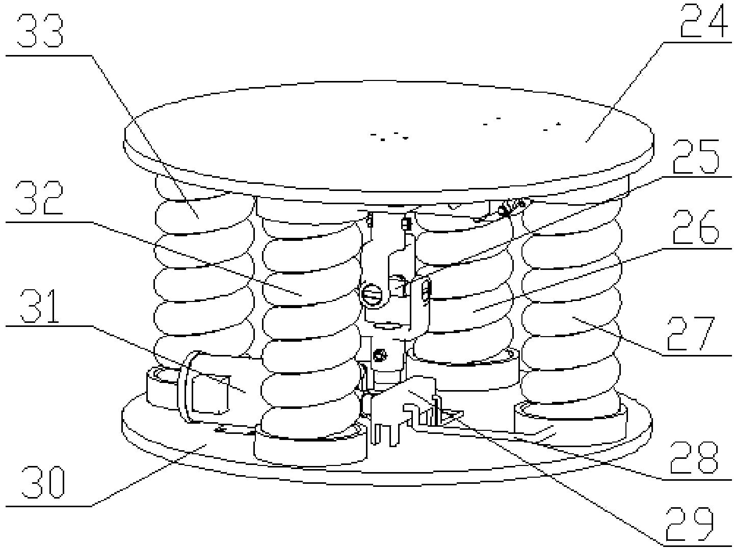
[0019] Implementation Case 1: Combining figure 1 , image 3 and Figure 4 , the present invention has the following several parts to form: elastic leg 1, forefoot trunk 3, spinal joint 4, rear trunk 6, the structure and motion principle of four legs are exactly the same. The pulley steering gear 2 is installed on the front and rear trunks such as figure 1 Below the position shown, its output shaft is connected to one end of the thigh 11 . The reel steering gear 8 is installed on the top of the front and back trunk as shown in the figure, and its output shaft connects the reel 5 . The front trunk 3 and the rear trunk 6 are connected together by spinal joints 4 . The spinal joint 4 is composed of a first end cover 24, a two-degree-of-freedom cross-axis rigid universal joint 25, a first bellows 26, a second bellows 32, a third bellows 27, a fourth bellows 33, hydraulic oil pipes 28, The two-position four-way electromagnetic valve 29, the second end cover 30, and the gear pum...

Embodiment example 2

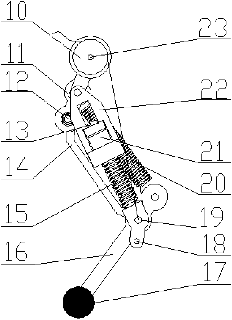
[0022] Implementation Case 2: Combining figure 2 , elastic leg 1 is made of wire rope 9, pulley 10, thigh 11, shank 14, foot 16, spherical foot 17, guide rod 13, linear bearing 21, linear bearing seat 22, stage clip 15, extension spring 20, limit pin 18 composition. One end of the thigh 11 is installed on the output shaft of the pulley steering gear 2, the pulley 10 is installed on the hip joint 23 of the thigh 11, the thigh 11 is connected with the shank 14 to form the knee joint 12, and one end of the shank 14 is connected to 1 / 3rd of the foot 16 One connection forms the ankle joint 19, and one end of the foot 16 is a rubber spherical foot 17. One end of the linear bearing seat 22 is connected to one-third of the thigh 11 through a rotating pair. The linear bearing 21 is installed on the linear bearing seat 22 through interference fit. One end of the guide rod 13 is sleeved in the linear bearing 21. The guide rod 13 The other end is connected with the foot 16 at the ankle...


PUM


Abstract

The invention provides a bionic four-foot robot provided with a spinal joint and elastic legs. The robot comprises a front trunk, a rear trunk, the spinal joint and the elastic legs. The front trunk and the rear trunk are connected through the spinal joint, the two ends of the lower portion of each trunk are respectively provided with one elastic leg, the spinal joint comprises end caps, a universal joint, corrugated pipes, hydraulic oil pipes, gear pumps and electromagnetic valves, the upper end cap and the lower end cap are connected in the center through the universal joint, the four corrugated pipes are evenly distributed between the upper end cap and the lower end cap, every two symmetric corrugated pipes are connected together through one hydraulic oil pipe, one gear pump and one electromagnetic valve, the two ends of each trunk are provided with winding reels, the winding reels are connected with output shafts of second steering engines, one end of each steel wire rope is fixed to the corresponding winding reel, and the other end of each steel wire rope is fixed to a corresponding ankle. The robot can move coordinatively and stably, moving characteristics of feline animals can be well simulated, and meanwhile impact of ground to the robot is reduced when the robot falls on the ground.

Description


Claims


Application Information

Patent Timeline
Owner HARBIN ENG UNIV
Why Eureka
Try Eureka