Rope counterweight sun wing auxiliary turning mechanism

A flipping mechanism and solar technology, applied in aerospace equipment, simulators of space navigation conditions, transportation and packaging, etc., can solve the problem that the solar wing drive mechanism does not have the ability to expand and retract, and achieve simple structure and easy operation Effect

Active Publication Date: 2016-01-20
HARBIN INST OF TECH
View PDF5 Cites 2 Cited by
  • Summary
  • Abstract
  • Description
  • Claims
  • Application Information

AI Technical Summary

Problems solved by technology

[0005] In order to solve the problem that the existing solar wing drive mechanism does not have the ability to deploy and fold on the ground, and needs a solar wing deployment mechanism for ground testing, the invention provides a rope counterweight type solar wing auxiliary turning mechanism

Method used


Image

  • Rope counterweight sun wing auxiliary turning mechanism
  • Rope counterweight sun wing auxiliary turning mechanism
  • Rope counterweight sun wing auxiliary turning mechanism

Examples


specific Embodiment approach 1

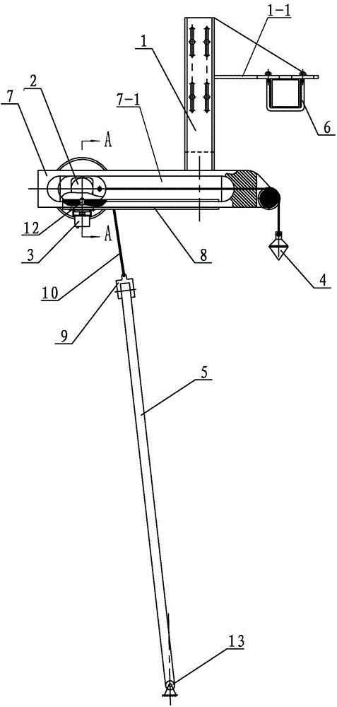
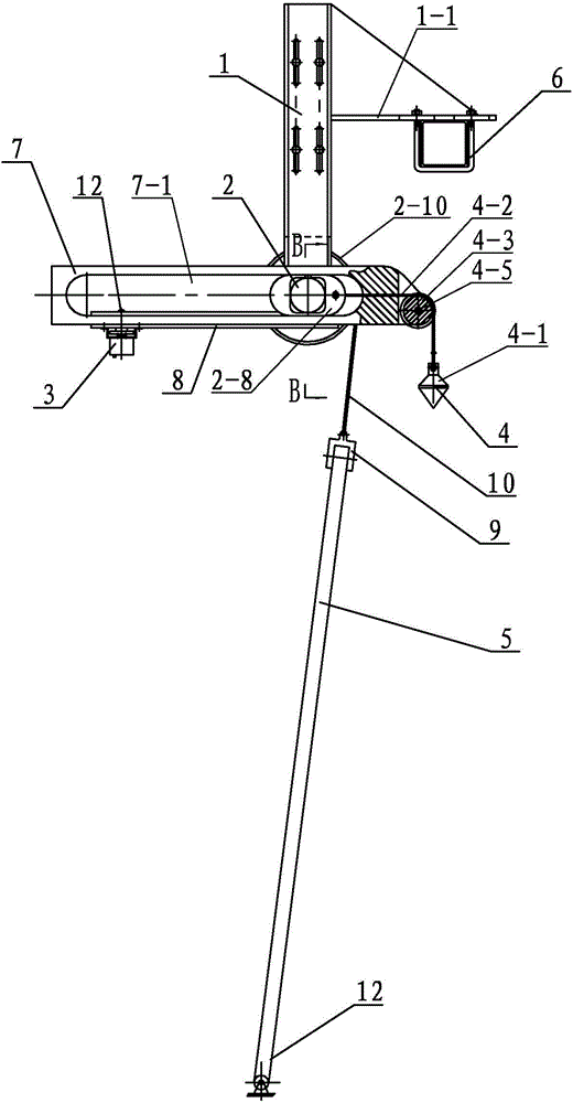
[0030] Specific implementation mode one: combine Figure 1 to Figure 10 Describe this embodiment. This embodiment includes a vertical carriage 1, a driving mechanism 2, a magnet 3, a counterweight mechanism 4, a solar wing 5, a horizontal carriage 7, a guide rail 8, a connector 9, a solar wing wire rope 10, and a lock 11, lock pin 12 and bearing 13,

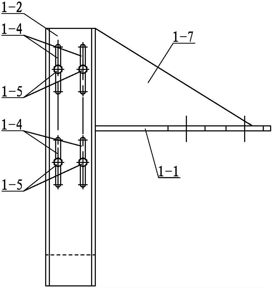
[0031] The vertical carriage 1 comprises a connecting plate 1-1, a front channel plate 1-2, a rear channel plate 1-3 and four connecting elements 1-5, and the front channel plate 1-2 and the rear channel plate 1- 3 Arranged back to back, four vertical slotted holes 1-4 are arranged on the front slotted plate 1-2 and the rear slotted plate 1-3, the four vertical slotted holes 1-4 are arranged in a rectangle, the front slotted plate 1 -2 is connected with the four connection elements 1-5 adopted by the rear channel plate 1-3, each connection element 1-5 is arranged in the corresponding vertical slot 1-4, and the connection plate 1...

specific Embodiment approach 2

[0038] Specific implementation mode two: combination figure 1 , figure 2 and Figure 11To describe this embodiment, when the driving mechanism 2 of this embodiment is located on the left side of the slideway 7-1, when the first angle α between the solar blade 5 and the horizontal line is 15°-25°, the solar blade 5 is in a folded state, See Figure 11 . Other components and connections are the same as those in the first embodiment.

specific Embodiment approach 3

[0039] Specific implementation mode three: combination figure 1 , figure 2 and Figure 11 Describe this embodiment, when the driving mechanism 2 of this embodiment is located on the left side of the slideway 7-1, when the first angle α between the solar blade 5 and the horizontal line is 20°, the optimal angle of the sun blade 5 is in the folded state ,See Figure 11 . Other components and connections are the same as those in the second embodiment.


PUM


Abstract

The invention provides a rope balance weight type solar wing auxiliary turning mechanism, and relates to a solar wing auxiliary turning mechanism. The problem that due to the fact that an existing solar wing driving mechanism can not be unfolded and folded on the ground, a solar wing unfolding mechanism used for ground tests is needed is solved. A horizontal sliding frame is arranged below a front channel plate on a vertical sliding frame. Slide ways are arranged on the front end face and the rear end face of the horizontal sliding frame. Driving mechanisms are arranged in the slide ways and slide along a guide rail leftward and rightward. The guide rail is fixedly connected with the horizontal sliding frame. A lock pin through hole is formed in the left side of the guide rail, and a lock pin is arranged in the lock pin through hole. A magnet is arranged below the lock pin. A solar wing steel wire rope is wound on a rope wheel of the driving mechanism, wherein one end of the solar wing steel wire rope is fixed to the rope wheel through a lock catch, the other end of the solar wing steel wire rope is connected with a solar wing through a connecting piece, the other end of the solar wing is fixed to a support, a balance weight mechanism is connected with a sliding block, and a pulley installation frame is arranged on the right side of the horizontal sliding frame. The rope balance weight type solar wing auxiliary turning mechanism is used for solar wing ground unfolding tests.

Description

technical field [0001] The invention relates to a solar wing auxiliary turning mechanism, in particular to a rope counterweight type solar wing auxiliary turning mechanism. Background technique [0002] In the thermal balance test of the lander, the solar wing needs to simulate the actual situation on the ground, and it needs to be deployed and retracted many times in the space environment simulator. Since the solar wing drive mechanism does not have the ability to deploy and retract on the ground, it is necessary to develop a set of ground tests. The mechanism is deployed with solar wings. [0003] In different working stages of the lander, the deployment state of the solar wing is different. The lander is in the cruising state during the earth-moon transfer and the moon-circling phase: the solar wing is in the unfolded state; the solar wing is retracted during the landing process; the solar wing is unfolded during the lunar surface work phase, and can be adjusted accordin...

Claims


Application Information

Patent Timeline
Patent Type & Authority Patents(China)
IPC IPC(8): B64G7/00
Inventor 丁亮高海波吕凤天刘振李楠邓宗全
Owner HARBIN INST OF TECH
Why Eureka
Try Eureka