
Needle core guiding mechanism of warp knitting machine

A guide mechanism, warp knitting machine technology, applied in the directions of warp knitting, knitting, textiles and papermaking, etc., can solve the problems of large support span, reduced production and output of warp knitting machines, and unstable movement, etc., and achieves running speed. And the effect of high work efficiency, speeding up the looping and weaving, and increasing production output

Active Publication Date: 2016-05-11
FUJIAN XIN GANG TEXTILE MACHINERY
View PDF8 Cites 0 Cited by
  • Summary
  • Abstract
  • Description
  • Claims
  • Application Information

AI Technical Summary

Problems solved by technology

[0003] At present, the guide seat of the core bed of most slot needle warp knitting machines is fixed on the slot needle bed, the guide shaft of the needle core bed moves in the guide seat, one end of the guide shaft is equipped with the needle core bed and the other end is fixed on the bracket, At present, the brackets on the market can only be installed with two guide shafts, and the needle core beds connected with the guide shafts have few support points, each support span is large, the vibration is large, easy to wear, and the service life is short. Unable to move smoothly, it is not conducive to the parallel relative movement between the groove needle and the needle core, which affects the knitting speed and quality of knitting, and the production and output of the warp knitting machine will also be reduced

Method used


Image

  • Needle core guiding mechanism of warp knitting machine
  • Needle core guiding mechanism of warp knitting machine
  • Needle core guiding mechanism of warp knitting machine

Examples


Embodiment Construction

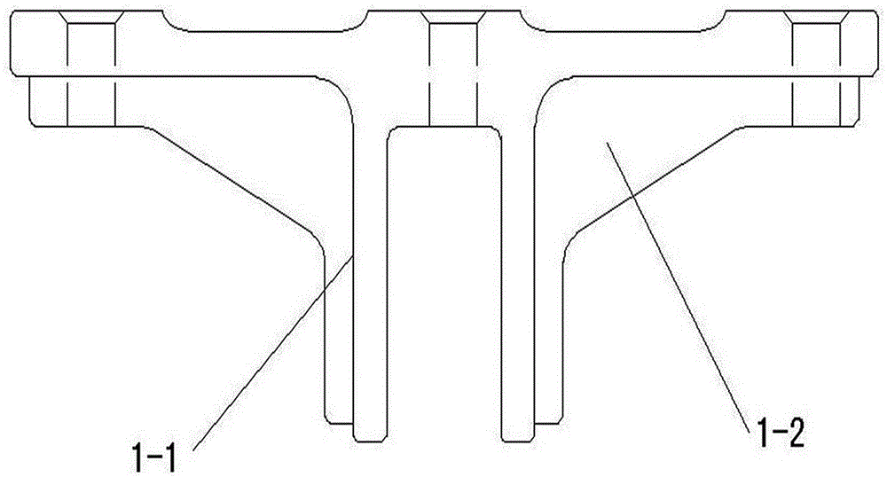
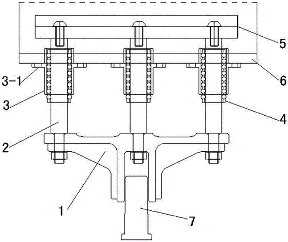
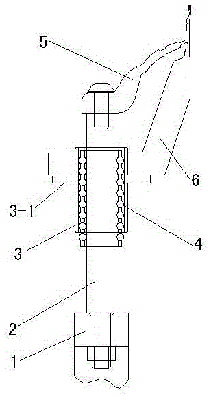
[0012] In order to deepen the understanding of the present invention, the present invention will be further described in detail below in conjunction with the accompanying drawings.

[0013] See attached figure 1 To attach image 3 Shown: a needle core guiding mechanism of a warp knitting machine, including: a bracket (1), a guide shaft (2), a guide seat (3), and a ball holder (4). The bracket (1) is in a "T" shape, the vertical plate (1-1) is perpendicular to the bottom plate (1-3), the vertical plate (1-1) is provided with a shaft hole, and the bracket (1) The vertical plate (1-1) at the bottom is connected to the transmission mechanism (7) through bearings, and holes for connecting the guide shaft (2) are provided equidistantly above the bracket (1). The guide shaft (2) has a threaded hole and a threaded segment, and the lower end of the guide shaft (2) is vertically positioned in the hole of the bracket (1), and is fastened and connected by a nut.

[0014] The guide shaf...


PUM


Abstract

The invention relates to a needle core guide mechanism of a warp knitting machine. According to the needle core guide mechanism, it is ensured that a needle core and a groove needle are kept moving oppositely in parallel. The needle core guide mechanism comprises supporting frames, guide shafts, guide bases and ball frames. The bottom of each supporting frame is connected with a transmission mechanism. A hole is formed in the upper portion of each supporting frame. The lower end of each guide shaft is located in the corresponding hole vertically, and the lower end of each guide shaft and the corresponding hole are fastened and connected through a nut. A flange boss is arranged in the middle of each guide base. The end face of the flange boss of each guide base is fixed to the bottom of a groove needle bed. One end of each guide base passes through the groove needle bed. Each ball frame is arranged in the corresponding guide base. The guide shafts penetrate through holes in the ball frames. The other end of each guide shaft is provided with an internal threaded hole. A needle core bed is fixed to the guide shafts through bolts. Generally, the multiple supporting frames which are distributed at intervals are needed to simultaneously transmit power so as to move the needle core bed. The holes in the upper portions of the supporting frames need to be located in the same straight line. Three guide shafts or two shafts with the shaft in the middle omitted can be installed above each supporting frame, the number of supporting points on the needle core bed is increased, each supporting span is decreased, and more stable running can be achieved.

Description

technical field [0001] The invention relates to the field of textile equipment, in particular to a needle core guiding mechanism of a warp knitting machine. Background technique [0002] During the knitting process of the slotted needle warp knitting machine, the slotted needle also swings back and forth with the stripping plate in addition to the lifting movement. The needle core is embedded in the needle groove of the slotted needle, and the needle core slides up and down relative to the slotted needle. When the needle core slides down in the groove relative to the grooved needle, the needle core head gradually sinks into the groove to open the needle port; The above-mentioned mutual circulation motion completes knitting, so the needle core should be able to slide briskly in the needle groove and fit well to form a loop; and the needle core must be strictly aligned with the needle groove during installation, so as to keep it parallel to the groove needle. [0003] Now mos...

Claims


Application Information

Patent Timeline
Patent Type & Authority Patents(China)
IPC IPC(8): D04B27/00
Inventor 郑依福郑春乐赖秋玉
Owner FUJIAN XIN GANG TEXTILE MACHINERY
Learn More