
A single degree of freedom magnetic bearing

A magnetic bearing and degree of freedom technology, applied in the direction of bearings, shafts and bearings, mechanical equipment, etc., can solve the problems of small axial bearing capacity, large magnetic leakage of magnetic bearings, low critical speed, etc., to ensure rigidity, reduce weight, The effect of shortening the axial length

Active Publication Date: 2016-08-17
江阴智产汇知识产权运营有限公司
View PDF6 Cites 2 Cited by
  • Summary
  • Abstract
  • Description
  • Claims
  • Application Information

AI Technical Summary

Problems solved by technology

[0003] The Chinese Patent Publication No. is CN102900761A, titled "A Permanent Magnet Bias Axial Hybrid Magnetic Bearing". There are magnetic isolation rings on both sides of the circular permanent magnet, but the magnetic flux leakage in the middle part of the magnetic bearing is very large, and the axial The length is long and the critical speed is low, so the application in flywheel system, machine tool electric spindle, centrifuge and other fields is limited
The Chinese patent publication number is CN101526107, and the name is "Hybrid Axial Magnetic Bearing with Permanent Magnets on the Rotor". It is difficult to assemble the permanent magnets on the rotor, and the rotor has low rigidity and small axial bearing capacity.

Method used


Image

  • A single degree of freedom magnetic bearing
  • A single degree of freedom magnetic bearing

Examples


Embodiment Construction

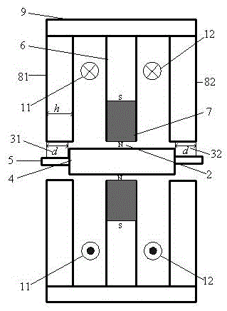
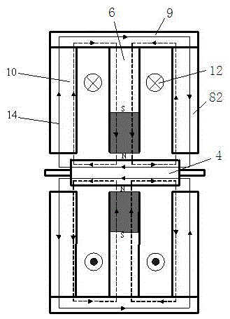
[0015] like figure 1 , 2 As shown, the present invention includes a rotor 4 and a permanent magnet 7. The rotor 4 is sleeved on the rotating shaft 5 and is formed by laminating silicon steel sheets. The outermost periphery is the axial stator cylinder 9, which is coaxially sleeved outside the rotor 4, the left end of the axial stator cylinder 9 is connected to the axial stator disk 81, and the right end of the axial stator cylinder 9 is connected to the axial The stator disc 82, the axial stator discs 81, 82 and the axial stator cylinder 9 are made of electrical pure iron to ensure good magnetic conductivity, low hysteresis, and minimize eddy current loss and hysteresis loss. The two outer end surfaces of the axial stator discs 81 and 82 are respectively flush with the left and right end surfaces of the axial stator cylinder 9 . The outer edges of the axial stator disk 81 and the axial stator disk 82 are fixedly connected to the inner wall of the axial stator cylinder 9 , an...


PUM


Abstract

The invention discloses a magnetic bearing with single freedom degree. An axial stator cylinder is arranged at the outmost periphery and is coaxially sleeved outside a rotor; the left and right ends of the axial stator cylinder are separately connected with an axial stator circular disc; the outer edges of the two axial stator circular discs are fixedly connected on the inner wall of the axial stator cylinder; gaps are formed between the inner edges of the two axial stator circular discs and the rotor; a radial stator disc is arranged at the axial center of the two axial stator circular discs; the outer edge of the radial stator disc is fixed on the inner wall of the axial stator cylinder and the inner edge is fixedly connected with a permanent magnet; a radial air gap is formed between the permanent magnet and the rotor; the permanent magnet is radially magnetized, the N pole is at the side of the rotor and the S pole is at the side of the radial stator disc; an axial control coil is respectively arranged between one axial stator circular disc and the radial stator as well as the other axial stator circular disc and the radial stator; the two axial control coils are respectively controlled by self switch power amplifier independently. According to the magnetic bearing with single freedom degree, the structure is simplified, the weight is lightened, the axial length is shortened and the critical rotating speed of a suspended rotor is increased.

Description

technical field [0001] The invention belongs to the field of electrical transmission equipment, and relates to a non-contact magnetic suspension bearing, in particular to a single-degree-of-freedom magnetic bearing, which can be used as a non-contact suspension support for high-speed transmission components such as flywheel systems, machine tool electric spindles, and centrifuges. Background technique [0002] The hybrid magnetic bearing provides the static bias magnetic flux by the permanent magnet, and the control magnetic flux by the control current, which has the advantages of reducing the control current and power loss. The hybrid single-degree-of-freedom magnetic bearing has the characteristics of simple structure and relatively low price. Compared with other multi-degree-of-freedom magnetic bearings, it has the highest engineering practical application value. [0003] The Chinese Patent Publication No. is CN102900761A, titled "A Permanent Magnet Bias Axial Hybrid Magn...

Claims


Application Information

Patent Timeline
Patent Type & Authority Patents(China)
IPC IPC(8): F16C32/04
Inventor 曾润章张维煜朱熀秋
Owner 江阴智产汇知识产权运营有限公司
Learn More