Ultra-high pressure steam vent valve

An ultra-high pressure, venting valve technology, applied in the direction of lift valve, valve details, valve device, etc., can solve problems such as valve closure, sealing surface damage, energy waste, etc., to reduce working noise, improve service life, reduce fluid flow The effect of scour loss

Active Publication Date: 2016-05-18
无锡卓尔阀业有限公司
View PDF6 Cites 0 Cited by
  • Summary
  • Abstract
  • Description
  • Claims
  • Application Information

AI Technical Summary

Problems solved by technology

[0002] In the prior art, ordinary vent valves generally adopt porous sleeve cage valves or low-noise cage valves. During use, the sealing surface of the valve core and valve seat is easily washed by high-speed fluid, which damages the sealing surface and causes the valve to be damaged. Lack of closure, large leakage, resulting in a lot of waste of energy
Especially in steam venting occasions with high temperature, high pressure difference, high sealing level requirements, and rapid opening, the existing ordinary vent valve is more difficult to apply, so it is necessary to design an ultra-high pressure steam vent valve

Method used


Image

  • Ultra-high pressure steam vent valve
  • Ultra-high pressure steam vent valve
  • Ultra-high pressure steam vent valve

Examples


Embodiment Construction

[0022] The present invention will be further described below in conjunction with specific drawings and embodiments.

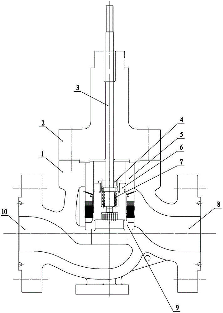
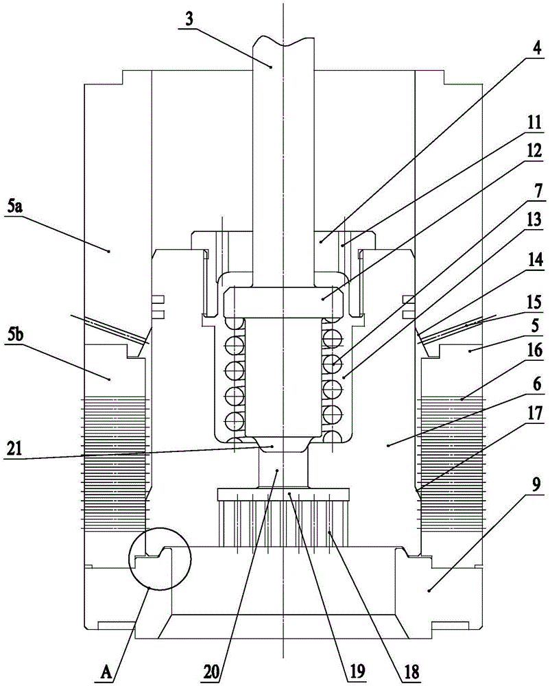
[0023] As shown in the figure: the ultra-high pressure steam vent valve in the embodiment is mainly composed of a valve body 1, a valve cover 2 and valve trims, wherein the valve trims are mainly composed of a valve stem 3, a valve seat 9, a porous sleeve 5 and a valve core 6 composition.

[0024] Such as figure 1 , figure 2 As shown, the center of the valve body 1 is provided with a valve cavity, the valve seat 9 and the porous sleeve 5 are installed in the valve cavity, the valve seat 9 is located below the porous sleeve 5, the valve core 6 is installed in the porous sleeve 5, and the valve The cover 2 is installed on the valve body 1 and seals the valve cavity, the valve stem 3 passes through the valve cover 2, and the lower end of the valve stem 3 is connected with the valve core 6; the valve body 1 is provided with a valve inlet 10 and a valve outlet 8,...


PUM


Abstract

The invention relates to an ultrahigh pressure steam emptying valve. The ultrahigh pressure steam emptying valve comprises a valve body, a valve deck and a valve trim. A valve cavity is formed in the center of the valve body. The valve trim comprises a valve rod, a valve seat, a porous sleeve and a valve element. The ultrahigh pressure steam emptying valve is characterized in that a pilot control room is arranged on the upper portion of the valve element, and a pilot through hole is formed in the center of the bottom of the pilot control room and communicated with a valve seat central hole through a pilot channel; the lower end of the valve rod is arranged in the pilot control room and sleeved with a pilot travel spring, the upper end of the pilot travel spring is connected with a step on the valve rod, the lower end of the pilot travel spring is jacked by the bottom of the pilot control room, and a sealing head is arranged at the lower end of the valve rod and can be matched with the edge of the upper end of the pilot through hole in a sealing mode; a transparent cover is installed on an opening of the upper end of the pilot control room, the position, below the step, of the valve rod is sealed in the pilot control room through the transparent cover and has the axial travel, and a pilot balance hole is formed in the transparent cover. The ultrahigh pressure steam emptying valve is suitable for high-temperature and high pressure difference steam emptying occasions with the high sealing requirement, and suitable for emptying other high pressure gases.

Description

technical field [0001] The invention relates to a venting valve, in particular to an ultra-high pressure steam venting valve suitable for high temperature, high pressure difference steam venting occasions or other high pressure gas venting occasions. Background technique [0002] In the prior art, ordinary vent valves generally use porous sleeve cage valves or low-noise cage valves. During use, the sealing surface of the valve core and valve seat is easily washed by high-speed fluid, which damages the sealing surface and causes the valve to If the seal is not tight, the leakage will be large, resulting in a large waste of energy. Especially in steam venting occasions with high temperature, high pressure difference, high sealing level requirements, and rapid opening, the existing ordinary vent valve is more difficult to apply, so it is necessary to design an ultra-high pressure steam vent valve. Contents of the invention [0003] The purpose of the present invention is to ...

Claims


Application Information

Patent Timeline
Patent Type & Authority Patents(China)
IPC IPC(8): F16K1/00F16K1/38F16K1/42F16K39/02F16K47/02F16K47/08
CPCF16K1/00F16K1/36F16K1/42F16K39/024F16K47/023F16K47/08
Inventor 吴杰谭志波邓凡沈志猷张勇
Owner 无锡卓尔阀业有限公司
Why Eureka
Try Eureka