Trigonometric function image demonstration device

A technology of trigonometric functions and demonstrator, which is applied to mathematical models, mathematical models, trigonometry, and geometry fields for projection or perspective, and can solve problems such as the inability to quantitatively display images of function changes.

Inactive Publication Date: 2014-07-23
张海湄
View PDF9 Cites 4 Cited by
  • Summary
  • Abstract
  • Description
  • Claims
  • Application Information

AI Technical Summary

Problems solved by technology

Its shortcomings: the demonstrator can only visually measure the changes in the vertical distance from the pivot point to the x-axis, and can roughly understand the changing trend of the function, but it cannot quantitatively display the function changing image

Method used


Image

  • Trigonometric function image demonstration device
  • Trigonometric function image demonstration device
  • Trigonometric function image demonstration device

Examples


Embodiment Construction

[0014] The present invention will be further described below in conjunction with the accompanying drawings and embodiments.

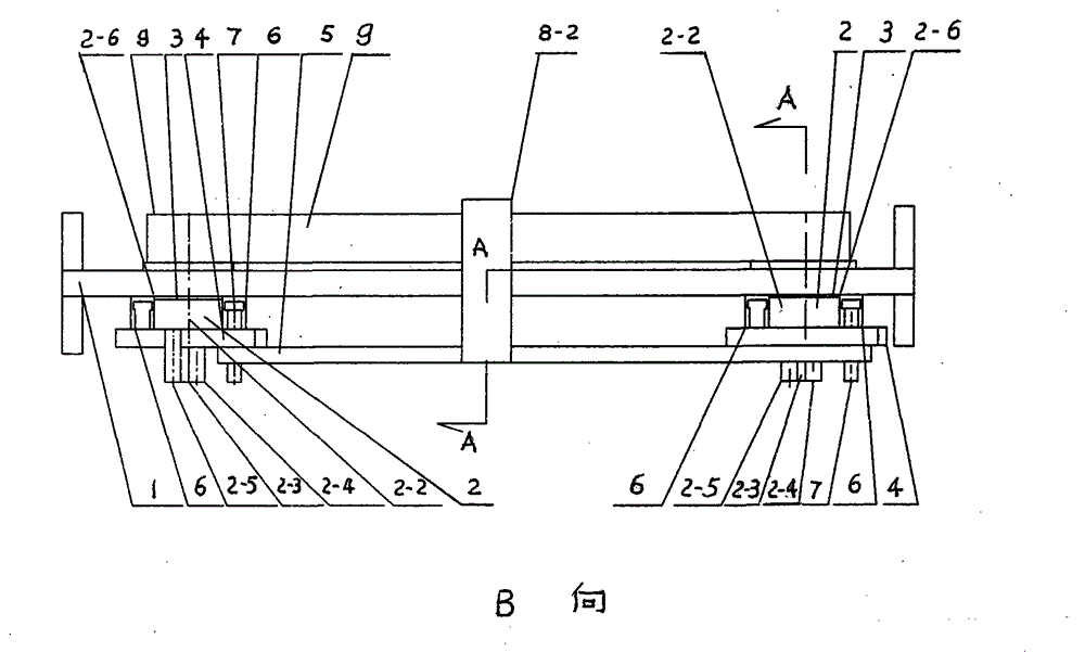
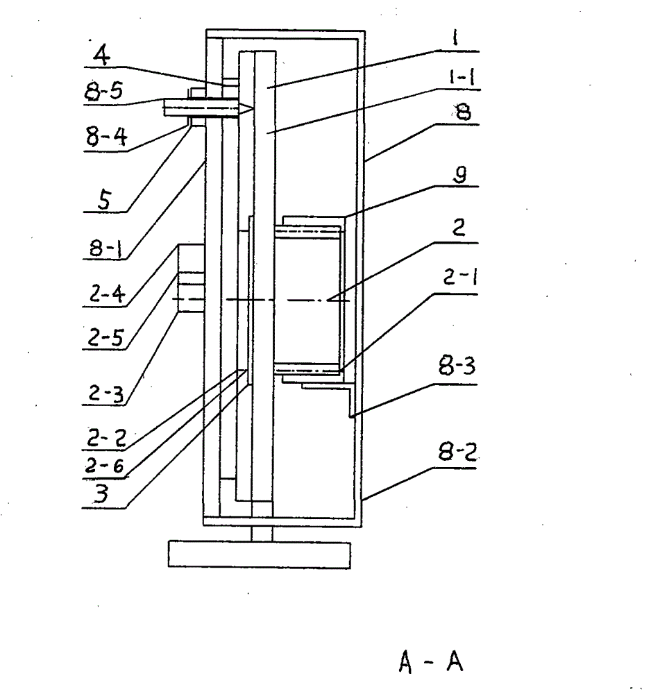
[0015] from figure 1 , figure 2 , image 3 As can be seen from the figure, the trigonometric function image demonstrator is composed of a drawing board assembly 1, a reference cylinder assembly 2, a lock piece 3, a reference cylinder rotation rod 4, a connecting rod 5, a tangent T-shaped guide rail 6, a cotangent T-shaped guide rail 7, a vertical Composition to slide bar assembly 8, toothed belt 9, slider cylinder 10. The two reference cylinder assemblies 2 are respectively inserted into the two holes of the drawing board assembly 1, and inserted into the locking piece 3 for axial fixation. When drawing the sine function image, two reference cylinder rotating rods 4 are respectively inserted into the center positioning cylinder and the sinusoidal positioning cylinder at the ends of the two reference cylinder assemblies 2, and then insert the connect...


PUM


Abstract

The invention discloses a trigonometric function image demonstration device. The trigonometric function image demonstration device comprises a drawing board assembly (1), reference cylinder assemblies (2), locking sheets (3), a reference cylinder dwang (4), a connection rod (5), tangent T-shaped guide rails (6), cotangent T-shaped guide rails (7), a vertical sliding rod assembly (8), a tooth form belt (9) and slide block cylinders (10). The two reference cylinder assemblies (2) are respectively inserted into the two holes of the drawing board assembly (1) and the locking sheets (3) are inserted into the reference cylinder assemblies (2) for axial fixation. The two tangent T-shaped guide rails (6) and the two cotangent T-shaped guide rails (7) are respectively tangent with the right sides and the left sides of the outer circles of the two reference cylinder assemblies (2), are parallel to the Y axis (1-4) of the drawing board assembly (1) and are in adhesive connection with the drawing board (1-1) of the drawing board assembly (1). The two guide rails are internally provided with the slide block cylinders (10). The advantages are as follows: trigonometric function images can be drafted in a quantification mode within positive and negative 360-degree scopes.

Description

technical field [0001] The technical solution of the present invention belongs to the field of mathematical models, specifically, belongs to the field of mathematical models for geometry, trigonometry, projection or perspective, and belongs to G09B23 / 04 according to the International Patent Classification. Background technique [0002] Existing trigonometric function demonstrator, as my country's patent No. 00221729.5 " omnipotent trigonometric function demonstrator ", it comprises a base plate that is done with plane Cartesian coordinate system and unit circle in advance, a hinge fulcrum is set at the center of circle, installs on the hinge fulcrum A bar with a length greater than the diameter of the unit circle and parallel to the end edge of the angle α of the bottom plate, and then set a hinge fulcrum at a length unit away from the center of the bar, and install a fulcrum on the hinge fulcrum with the fulcrum as the center, A sinusoidal bar of length equal to two length un...

Claims


Application Information

Patent Timeline
Patent Type & Authority Applications(China)
IPC IPC(8): G09B23/04
Inventor 张海湄
Owner 张海湄
Why Eureka
Try Eureka