Supercharge Your Innovation With Domain-Expert AI Agents!

Leakage protection socket with jack baffle device

A technology of baffle device and leakage protection, which is applied to the components of the connection device, coupling device, circuit, etc., can solve the problems of high processing cost, high processing precision, complex structure, etc., and achieve large movement space, reasonable structure, and structure simple effect

Active Publication Date: 2015-12-30
WENZHOU VAN SHEEN ELECTRIC APPLIANCE
View PDF7 Cites 0 Cited by
  • Summary
  • Abstract
  • Description
  • Claims
  • Application Information

AI Technical Summary

Problems solved by technology

[0002] Existing earth leakage protection sockets with jack baffle devices generally include a housing, a middle support with conductive sockets installed, left and right baffles for blocking / opening conductive sockets, and left and right baffles for carrying left and right sockets. The baffle guide rail of the baffle, such as the baffle device disclosed in the invention patents with patent numbers of 201110061919.8 and 201110061948.4, the left and right baffles are reset by the elastic legs extending in opposite directions, and the movement track of the left and right baffles is limited by the internal space and mechanism. The combined range is small, and for the leakage protection socket of the left I and right T-shaped jacks, a small baffle needs to be installed separately, resulting in a more complicated structure, higher processing costs, and high processing accuracy. The assembly process is more complicated

Method used


Image

  • Leakage protection socket with jack baffle device
  • Leakage protection socket with jack baffle device
  • Leakage protection socket with jack baffle device

Examples


Embodiment Construction

[0025] Below in conjunction with specific embodiment and accompanying drawing, the present invention will be further described:

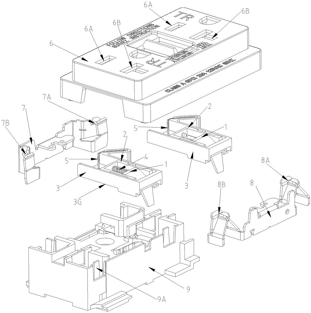
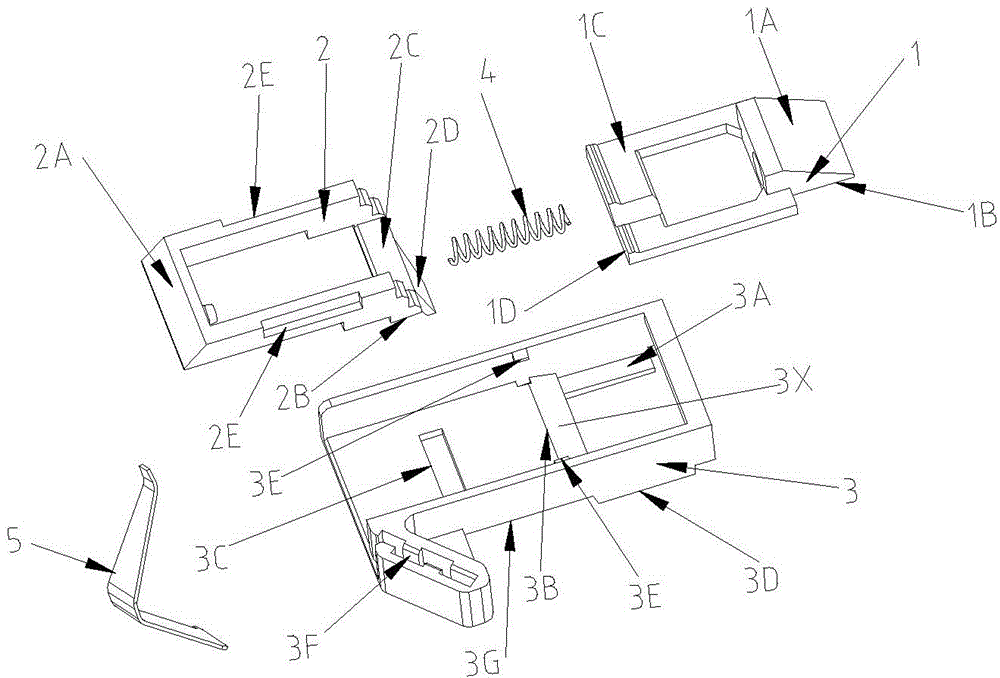
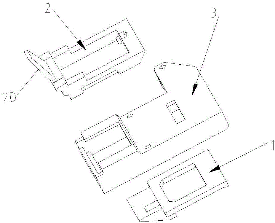
[0026] Refer to attached Figure 1 to Figure 10 As shown, the leakage protection socket with jack baffle device of the present invention includes a housing (only the upper cover 6 is shown in the figure), and conductive sockets (7A, 7B, 8A, 8B) are installed for blocking / Open the left baffle 1, the right baffle 2 and the baffle guide rail 3 for carrying the left and right baffles of the conductive socket. The left baffle 1 includes a hollow frame 1C and a stopper 1B located at the front end of the hollow frame. The stopper has a guide The guide slope surface 1A, the conductive socket under the block 1B is T-shaped, the left baffle block 1B has a length that can cover the T-shaped conductive socket as a whole; the right baffle 2 includes a hollow frame, and the front end of the hollow frame has a guide slope On the surface 2A, the tail end of the ...


PUM


Abstract

The invention provides an electric leakage protection socket with a socket aperture baffle device. The socket comprises a shell, a middle-layer support, a left baffle, a right baffle and a baffle guide rail, wherein the middle-layer support is provided with a conductive plug bush, and the left baffle and the right baffle are used for plugging or opening the conductive plug bush. The left baffle comprises a hollow frame and a stop block located at the front end of the hollow frame, and the stop block of the left baffle is provided with a guide slope and is long enough to guarantee that the T-shaped conductive plug bush is completely covered with the stop block. The front end of a hollow frame of the right baffle is provided with a guide slope, the tail end of the hollow frame is provided with an elastic supporting pin, and the lower end of the hollow frame of the right baffle is provided with a first step-shaped notch. The baffle guide rail is provided with an elastic metal piece, and the free end of the elastic metal piece abuts against the outer side wall of the tail end of the hollow frame of the left baffle. The socket has the advantages that a T-shaped socket aperture is completely covered with the stop block of the left baffle, a small baffle is not needed, and the socket is simple in structure and reliable in movement; the baffles are reasonable in structure, and the left baffle is restored through the elastic metal piece and has a large movement space.

Description

technical field [0001] The invention relates to the technical field of power sockets, in particular to a leakage protection socket with a socket baffle device. Background technique [0002] Existing earth leakage protection sockets with jack baffle devices generally include a housing, a middle support with conductive sockets installed, left and right baffles for blocking / opening conductive sockets, and left and right baffles for carrying left and right sockets. The baffle guide rail of the baffle, such as the baffle device disclosed in the invention patents with patent numbers of 201110061919.8 and 201110061948.4, the left and right baffles are reset by the elastic legs extending in opposite directions, and the movement track of the left and right baffles is limited by the internal space and mechanism. The combined range is small, and for the leakage protection socket of the left I and right T-shaped jacks, a small baffle plate needs to be set in addition, thus resulting in ...

Claims


Application Information

Patent Timeline
Patent Type & Authority Patents(China)
IPC IPC(8): H01R13/447
Inventor 黄华道
Owner WENZHOU VAN SHEEN ELECTRIC APPLIANCE
Features
  • R&D
  • Intellectual Property
  • Life Sciences
  • Materials
  • Tech Scout
  • Unparalleled Data Quality
  • Higher Quality Content
  • 60% Fewer Hallucinations
Learn More