Motor rotor and motor

A technology of motor rotor and inner iron core, applied in the field of motors, can solve the problems of few applications and immature technology

Active Publication Date: 2014-07-23
PANASONIC APPLIANCES MOTOR HANGZHOU
View PDF4 Cites 0 Cited by
  • Summary
  • Abstract
  • Description
  • Claims
  • Application Information

AI Technical Summary

Problems solved by technology

[0005] The motor rotor is designed as a split type. This method is currently less used in solving the problem of electrical corrosion, and the technology is not mature enough.

Method used


Image

  • Motor rotor and motor
  • Motor rotor and motor
  • Motor rotor and motor

Examples


Embodiment Construction

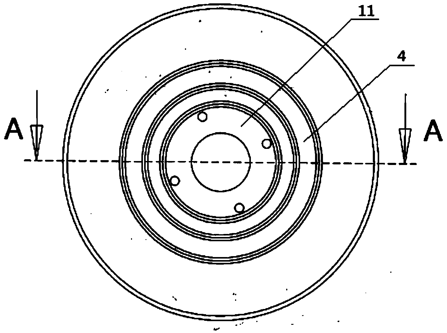
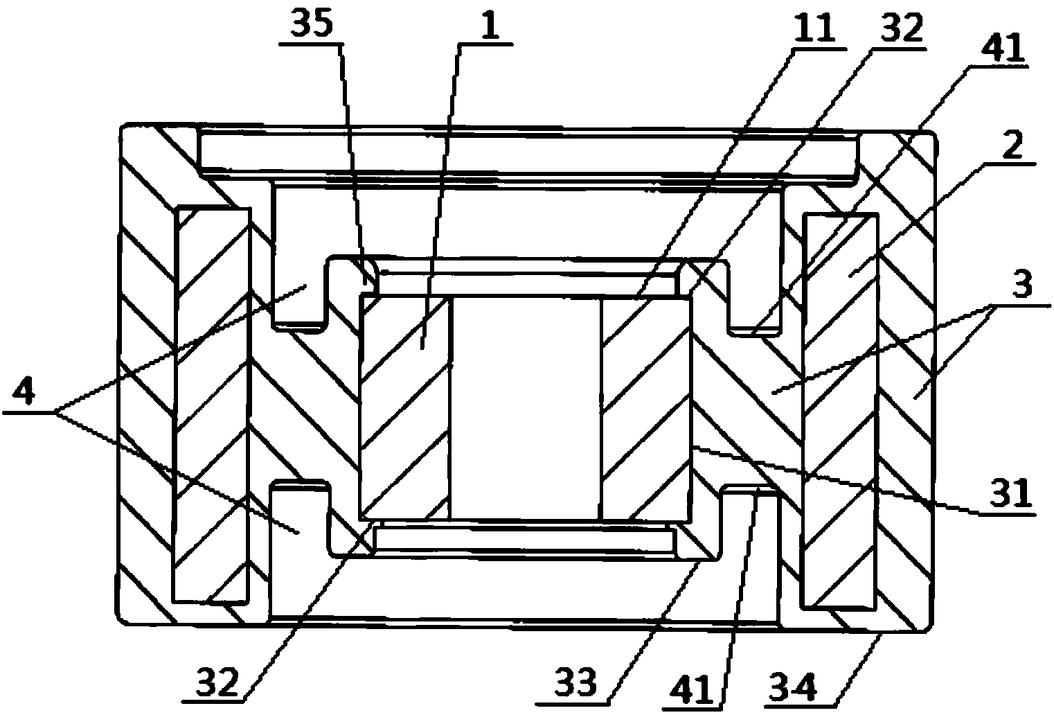
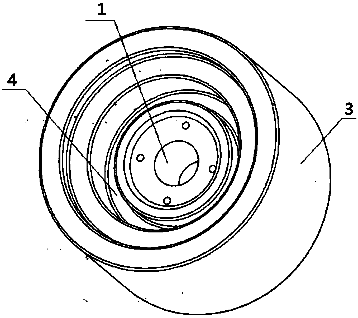
[0020] Such as Figure 1 to Figure 5 Shown is an embodiment of the motor rotor of the present invention, which is applied to a motor, wherein figure 2 and Figure 5 exactly the same, both figure 1 The A-A sectional view in the middle is divided into two for the sake of clear marking. The motor rotor of the present invention includes an inner iron core 1 and an outer iron core 2 arranged concentrically. Both the inner iron core 1 and the outer iron core 2 can be of an integral iron core or laminated structure. The inner iron core 1 and the outer iron core 2 are fixed by the insulating framework 3, the thickness h of the inner iron core 1 and the thickness H of the outer iron core 2 satisfy the following relationship: 0.5≤h: H figure 2 The upper and lower symmetrical structures shown in , the symmetrical structure here only expresses the relative positional relationship between the inner iron core 1 and the outer iron core 2, and does not involve the insulating skeleton 3 and...


PUM


Abstract

The invention discloses a motor rotor which comprises an inner iron core and an outer iron core. The inner iron core and the outer iron core are arranged concentrically and are fixed through an insulation frame. The motor rotor is characterized in that the thickness h of the inner iron core and the thickness H of the outer iron core satisfy the relation that h : H is larger than or equal to 0.5 and smaller than 1, and the distance between a plane where either end face of the inner iron core is placed and a plane where an end face on the same side of the outer iron core is placed is 0.5 H-0.5 h. According to the designing scheme that the thickness of the inner iron core is smaller than the thickness of the outer iron core, shaft voltage can be lowered, and poor motor electric corrosion is reduced.

Description

technical field [0001] The present invention relates to motors, and more particularly to motor rotors. Background technique [0002] The occurrence of electric corrosion in the motor will cause bearing damage, make the motor produce abnormal noise, and affect the life of the motor. Traditional countermeasures include: [0003] Ceramic bearings are used to block the discharge path between the inner and outer hubs of the bearings, but ceramic bearings are expensive, which will greatly increase the manufacturing cost of the motor. [0004] The motor stator is connected to the end covers on both sides by using the conduction plate to reduce the shaft voltage, but after applying this method, the electric corrosion phenomenon of the motor is still frequent. [0005] The motor rotor is designed as a split type. This method is currently less used to solve the problem of electrical corrosion, and the technology is not mature enough. Contents of the invention [0006] The technic...

Claims


Application Information

Patent Timeline
Patent Type & Authority Applications(China)
IPC IPC(8): H02K1/22
Inventor 吴家福叶文军李林军童健
Owner PANASONIC APPLIANCES MOTOR HANGZHOU
Why Eureka
Try Eureka