
Roller bearing unit

A rolling bearing and axial technology, applied in the field of rolling bearing units, can solve problems such as the temperature rise of the outer ring 2 and the hub 3, the gap between the fitting parts, etc., and achieve the effects of reducing weight, preventing electric corrosion, and improving durability

Active Publication Date: 2014-04-02
NSK LTD
View PDF4 Cites 8 Cited by
  • Summary
  • Abstract
  • Description
  • Claims
  • Application Information

AI Technical Summary

Problems solved by technology

[0010] However, the temperature of the outer ring 2 and the hub 3 rises during use
Therefore, due to the difference in the coefficient of linear expansion between the outer ring track member 6 and the outer ring main body 5 made of different materials, or between the outer inner ring track member 10 and the inner inner ring track member 11 and the hub main body 9, it may cause a The preload of the rolling element 4 changes, or a gap is created in the fitting part between these parts

Method used


Image

  • Roller bearing unit
  • Roller bearing unit
  • Roller bearing unit

Examples


Embodiment Construction

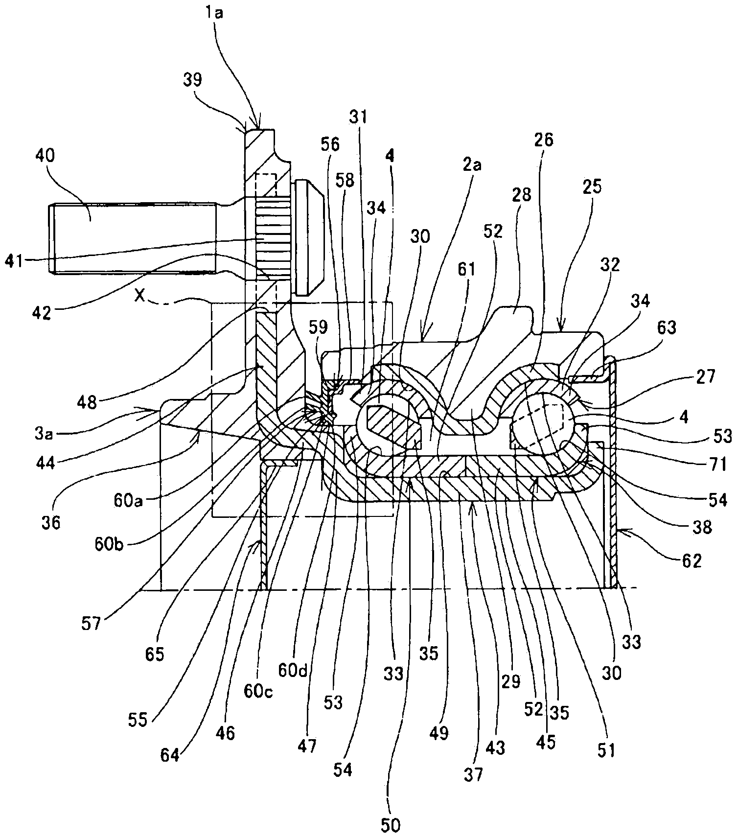
[0060] Hereinafter, the rolling bearing unit of the present invention will be described by taking several embodiments of the hub unit for supporting a wheel as examples. The rolling bearing unit of the present invention is characterized in that, in order to achieve both weight reduction and durability improvement, materials capable of weight reduction are used as its constituent parts, and the structure of the stationary side raceway ring and / or the rotation side raceway ring is considered.

[0061] [First example of embodiment]

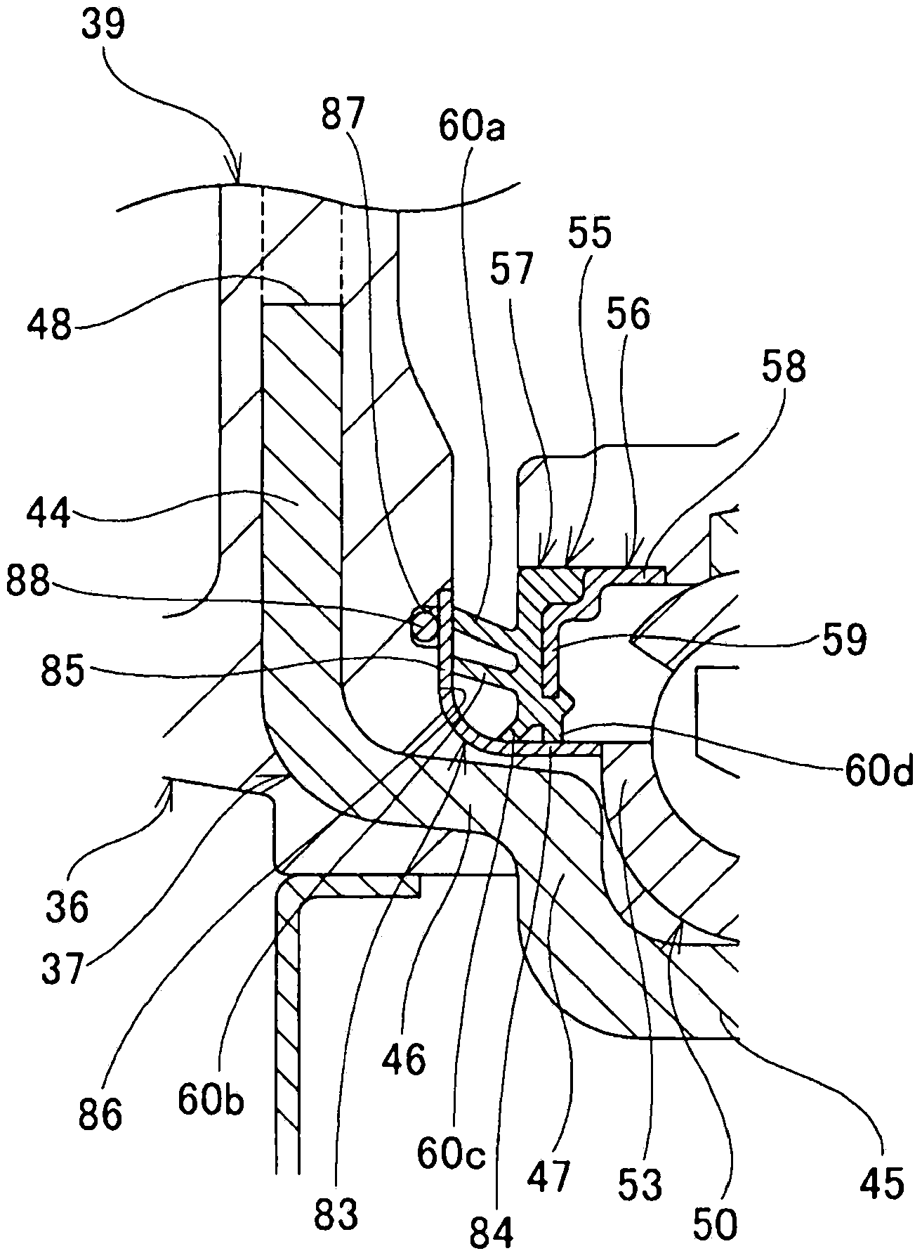
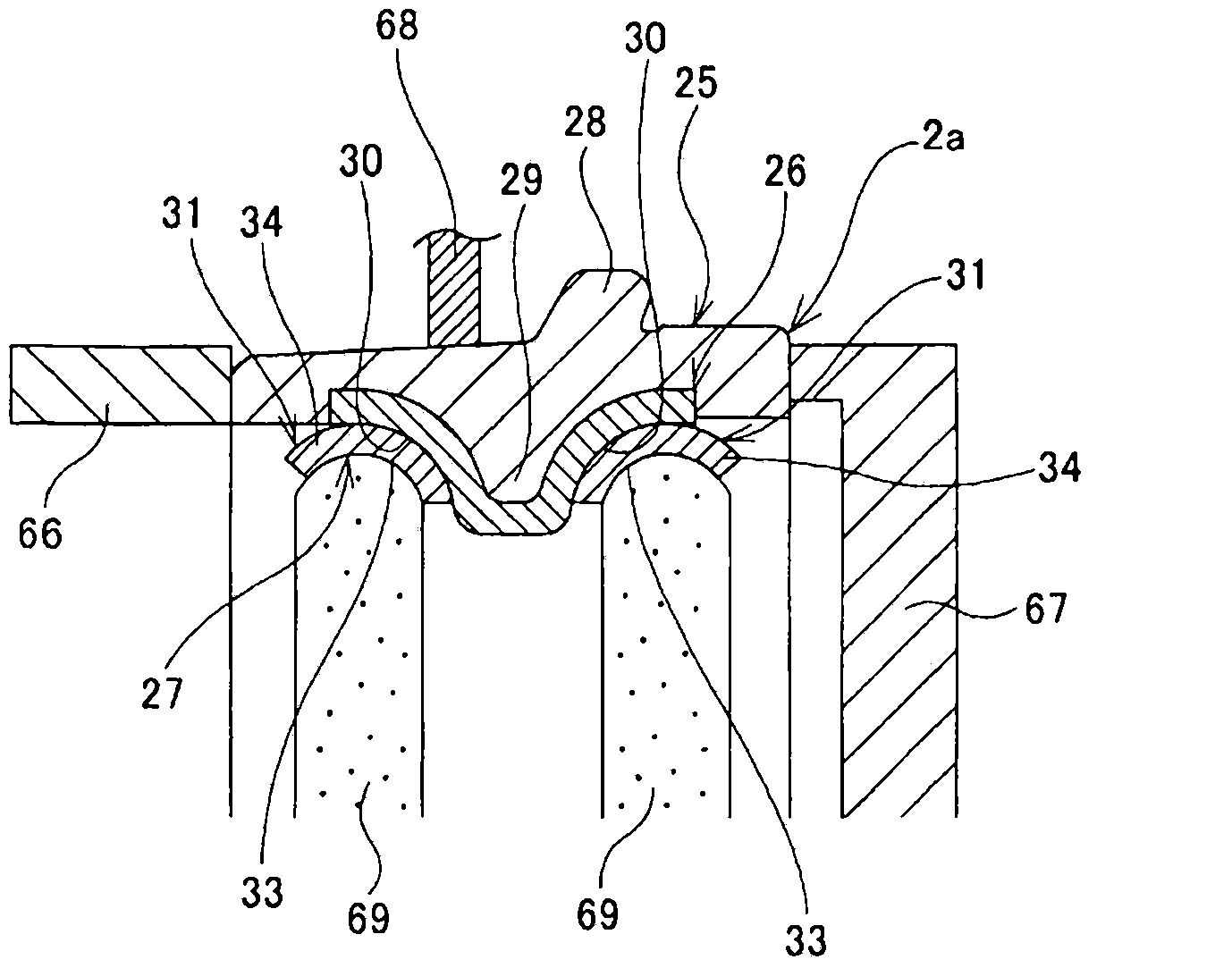
[0062] Figure 1 to Figure 6 The first example of the embodiment of the present invention is shown. The hub unit 1a for supporting a wheel of this example is used for a driven wheel and has the same Figure 11 The shown conventional structure has the same basic structure. The hub unit 1a for supporting a wheel has: an outer ring 2a that is a stationary side raceway; a hub 3a that is a rotating side raceway arranged on the inner diameter side of the...


PUM

PropertyMeasurementUnit
thicknessaaaaaaaaaa

Abstract

The invention provides a roller bearing unit for which the weight can be decreased and the durability can be improved. An outer ring core metal (26) that is manufactured from an iron alloy and forms an outer ring (2a) is molded to an outer ring main body (25) manufactured from a synthetic resin containing reinforced fibers or from an aluminum alloy. At the inner circumferential surface of the outer ring core metal (26), outer ring raceway members (27) are fitted into and affixed to mating concave surfaces (30), which are the portions of the inner circumferential surface of the outer ring core metal (26) that are exposed from the outer ring main body (25). A hub core metal (37) that is manufactured from an iron alloy and forms a hub (3a) is molded to a hub main body (36) manufactured from a synthetic resin containing reinforced fibers or from an aluminum alloy. At the outer circumferential surface of the hub core metal (37), inner ring raceway members (38) are fitted onto and affixed to a mating surface (49), which is the portion of the outer circumferential surface of the hub core metal (37) that is exposed from the hub main body (36).

Description

technical field [0001] The present invention relates to a rolling bearing unit used in a hub unit for supporting a wheel for supporting an automobile wheel on a suspension device. Background technique [0002] In order to rotatably support an automobile wheel on a suspension device, a hub unit for supporting the wheel is used. As a basic structure of a hub unit for supporting a wheel, a rolling bearing unit is used which rotatably supports a rotating side raceway via rolling elements on the inner or outer diameter side of the stationary side raceway. exist Figure 11 In the figure, the structure of the hub unit for supporting a wheel disclosed in Unexamined-Japanese-Patent No. 2003-74570 is shown. This hub unit 1 for supporting a wheel includes an outer ring 2 as a stationary side raceway, a hub 3 as a rotating side raceway disposed on the inner diameter side of the outer ring 2 , and a hub for freely rotatably supporting the outer ring 2 . 3 multiple rolling elements 4 . ...

Claims


Application Information

Patent Timeline
Patent Type & Authority Applications(China)
IPC IPC(8): F16C33/60B60B35/02B60B35/14B60B35/18F16C19/18F16C33/62F16C33/78F16C35/063
CPCB60B2380/75F16C33/62F16C33/7876F16C2326/02B60B2900/321B60B27/0005B60B2360/32F16C33/60B60B2900/111F16C19/185F16C33/588B60B2380/73F16C2220/04F16C33/7826
Inventor 石川宽朗若林达男
Owner NSK LTD
Learn More