Automatic placement machine

A placement machine, fully automatic technology, applied in the direction of electrical components, electrical components, electrical components to assemble printed circuits, etc., can solve the problems of high cost, low placement accuracy, complex structure, etc., achieve low cost, increase placement The effect of improving installation efficiency and simplifying motion trajectory

Active Publication Date: 2017-01-11
BEIJING TINYO ELECTRONICS
View PDF3 Cites 0 Cited by
  • Summary
  • Abstract
  • Description
  • Claims
  • Application Information

AI Technical Summary

Problems solved by technology

The existing automatic placement machine has complex structure and high cost, but the placement accuracy of the simple structure and low cost placement machine is not high, and it can only mount some electronic components. Therefore, a low-cost, high placement accuracy is now needed. Automatic flaking machine

Method used


Image

  • Automatic placement machine
  • Automatic placement machine
  • Automatic placement machine

Examples


Embodiment Construction

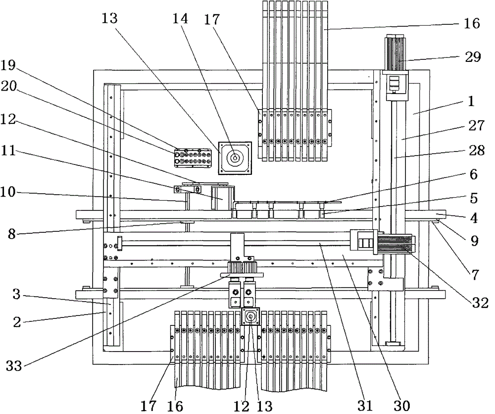
[0025] Such as figure 1 As shown, the fully automatic placement machine described in the embodiment of the present invention includes a base plate 1, and the two sides of the base plate 1 are symmetrically provided with a door-shaped base frame 2, and the upper end surface of the door-shaped base frame 2 on one side is fixedly connected to the second A linear slide rail 3, and the upper end surface of the door-shaped base frame 2 on the other side is fixedly connected with the first lead screw 28 device, the first lead screw 28 device is parallel to the first linear slide rail 3, and the first lead screw 28 device is parallel to the first linear slide rail 3, and the first lead screw 28 device A second lead screw 31 device is vertically arranged between the lead screw 28 device and the first linear slide rail 3, and the second lead screw 31 device is threadedly connected with a double-head placement mechanism, and the bottom of the door-shaped base frame 2 Vertically be provid...


PUM


Abstract

The invention relates to a full automatic chip mounter which comprises a base plate. n-shaped base frames are symmetrically arranged on two sides of the base plate, a first linear sliding rail is fixedly connected onto the upper end face of an n-shaped base frame on one side, a first lead screw device is fixedly connected onto the upper end face of an n-shaped base frame on the other side, a second lead screw device is vertically arranged between the first lead screw device and the first linear sliding rail, the second lead screw device is in threaded connection with a double-end mounting mechanism, a conveying track mechanism is vertically arranged under the n-shaped base frames, and visual recognition devices and material supply tables are arranged on two sides of the conveying track mechanism respectively. A material supply device is arranged on each material supply table, and a suction nozzle exchange device is arranged on one side of the conveying track mechanism. Due to the fact that the material supply devices and the visual recognition devices are arranged on two sides of a conveying track, the moving track of the mounting head is simplified, the mounting efficiency is improved, and meanwhile automatic recognition and accurate location of electronic elements are achieved. Mounting of the electronic elements of different sizes can be achieved by arranging suction nozzles of different sizes, and the whole mounter is compact in structure, low in cost and high in mounting accuracy.

Description

technical field [0001] The invention relates to electronic placement equipment, in particular to a fully automatic placement machine. Background technique [0002] As a pillar equipment in the field of electronic placement, the placement machine has the advantages of fast placement speed, high placement accuracy, stable and reliable placement quality, which has completely changed the characteristics of labor-intensive enterprises in the placement field and greatly improved Production efficiency, liberating the labor force, is an indispensable equipment for the modern placement industry. The existing automatic placement machine has complex structure and high cost, but the placement accuracy of the simple structure and low cost placement machine is not high, and it can only mount some electronic components. Therefore, a low-cost, high placement accuracy is now needed. Automatic flaking machine. Contents of the invention [0003] The purpose of the present invention is to p...

Claims


Application Information

Patent Timeline
Patent Type & Authority Patents(China)
IPC IPC(8): H05K3/30H05K13/04
Inventor 王恩来
Owner BEIJING TINYO ELECTRONICS
Why Eureka
Try Eureka