
hydraulic equipment

A hydraulic equipment, hydraulic technology, applied in the direction of brakes, bolts, etc., can solve problems such as the inability to guarantee repeatable quality, and achieve the effect of reducing the risk of assembly errors, small tolerances, and reducing material costs

Active Publication Date: 2016-08-24
ROBERT BOSCH GMBH
View PDF4 Cites 0 Cited by
  • Summary
  • Abstract
  • Description
  • Claims
  • Application Information

AI Technical Summary

Problems solved by technology

The orientation and alignment of the two components relative to each other is produced during assembly by means of electrical and hydraulic valve components, wherein a reproducible quality during assembly cannot be guaranteed here

Method used


Image

  • hydraulic equipment
  • hydraulic equipment
  • hydraulic equipment

Examples


Embodiment Construction

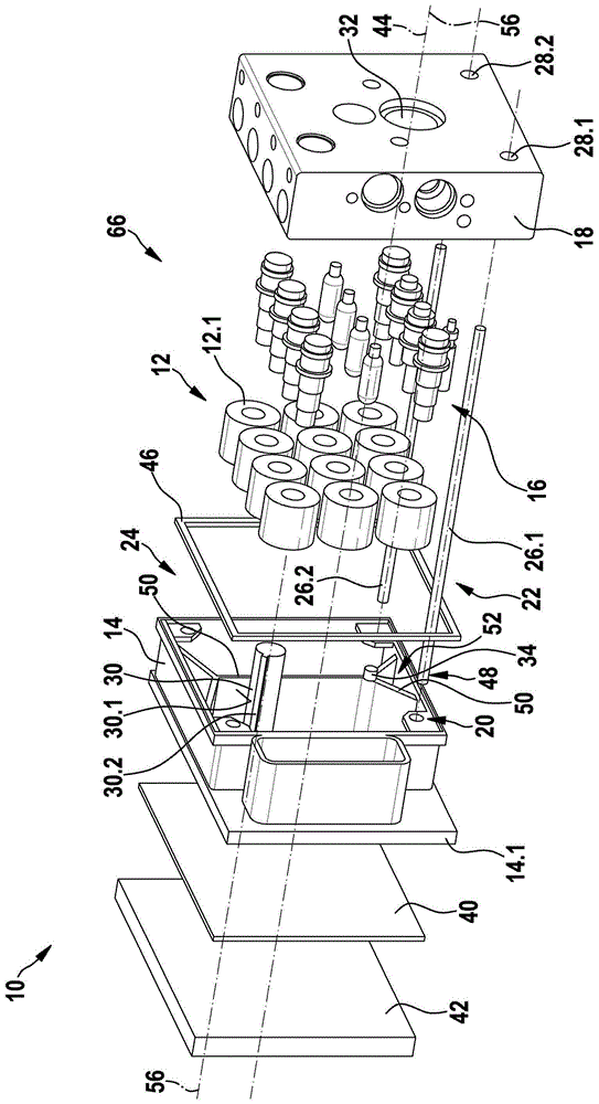
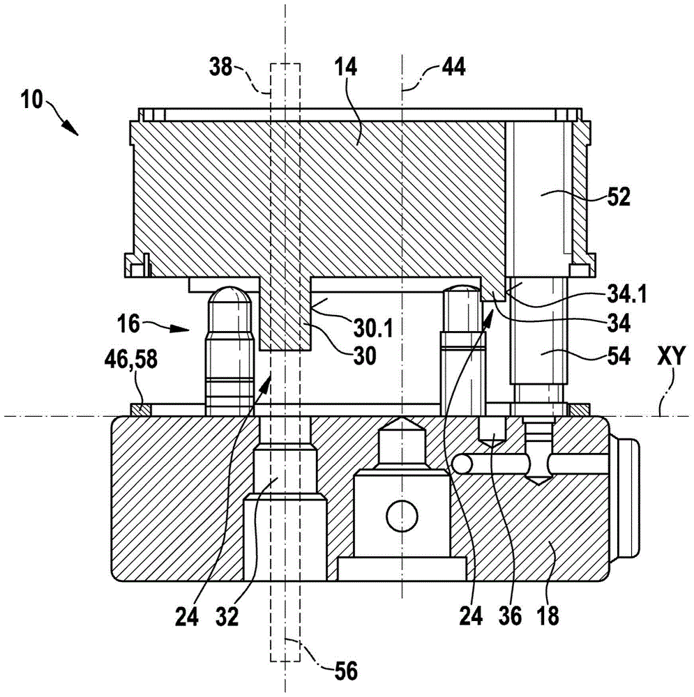
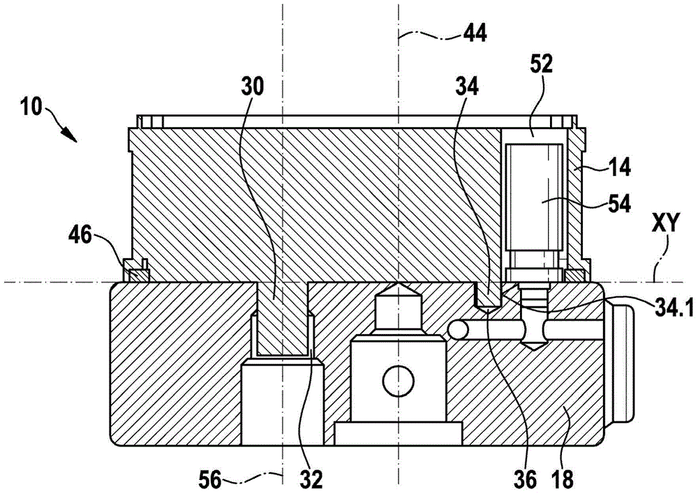
[0022] as available from Figures 1 to 4 As seen in FIG. 1 , the hydraulic system 10 includes a controller housing 14 carrying the electrical valve components 12 and a hydraulic block 18 carrying the hydraulic valve components 16 . In the exemplary embodiment shown, hydraulic system 10 is a component of a hydraulic system of a motor vehicle, for example an anti-lock brake system (ABS) or an anti-skid control system (ASR system) or an electronic stability program system (ESP system). The controller housing 14 is preferably formed as a simple plastic component and the hydraulic block 18 is preferably made of aluminum.

[0023] The hydraulic block 18 has various bores and channels in which in particular the hydraulic valve part 16 of the solenoid valve 66 is at least partially inserted and preferably packed. The electrical valve part 12 in the form of a coil 12 . 1 of the respective solenoid valve 66 is axially pushed onto the hydraulic valve part 16 .

[0024] A cover 42 with ...


PUM


Abstract

The invention relates to a hydraulic unit (10) comprising a control device housing (14) which bears electrical valve components (12), a hydraulic block (18) which bears hydraulic valve components (16) and a device (20) for connecting the control device housing (14) to the hydraulic block (18). A device (22) for approximate pre-centring and a device (24) for the final alignment of the two assemblies (14, 18) with each other are provided.

Description

technical field [0001] The invention relates to a hydraulic device according to the preamble of independent claim 1 . Background technique [0002] When manufacturing conventional hydraulic devices such as those used in anti-lock braking systems (ABS) or anti-skid control systems (ASR systems) or electronic stability program systems (ESP systems) of vehicles, the controller housing is usually screwed with the hydraulic block. In this case, the control housing is pretensioned and fastened to the hydraulic block with a tightening torque by means of screws via sleeves in the control housing with corresponding threaded holes in the hydraulic block. During assembly, the orientation and alignment of the two components relative to one another is produced by the electrical and hydraulic valve components, wherein a reproducible quality during assembly cannot be guaranteed here. In this case, the controller housing is screwed to the hydraulic block either from the inside or from the ...

Claims


Application Information

Patent Timeline
Patent Type & Authority Patents(China)
IPC IPC(8): B60T8/36
CPCB60T8/368F16B19/02
Inventor M·迈尔A·韦R·菲斯特B·卢茨
Owner ROBERT BOSCH GMBH
Learn More