Rotary electric machine

A technology for rotating electrical machines and power supply terminals, applied in electrical components, electromechanical devices, electrical components, etc., can solve the problems of large-scale equipment and high manufacturing costs, and achieve the effect of small occupied space and reduced manufacturing costs.

Active Publication Date: 2014-07-23
HONDA MOTOR CO LTD
View PDF8 Cites 10 Cited by
  • Summary
  • Abstract
  • Description
  • Claims
  • Application Information

AI Technical Summary

Problems solved by technology

Therefore, it is necessary to attach a large component close to the stator core, which is likely to cause an increase in the size and weight of the device
[0010] In addition, in the above-mentioned conventional rotating electric machine, it is necessary to provide a complex shape of the connection portion for connecting the wires of each coil to the midpoint bus ring, so the manufacturing cost may also be increased.

Method used


Image

  • Rotary electric machine
  • Rotary electric machine
  • Rotary electric machine

Examples


Embodiment Construction

[0054] Hereinafter, a rotating electrical machine according to an embodiment of the present invention will be described based on the drawings.

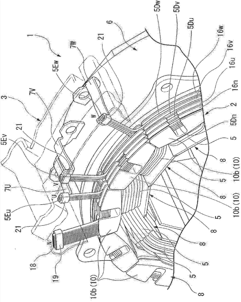
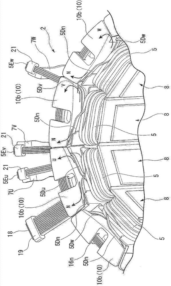
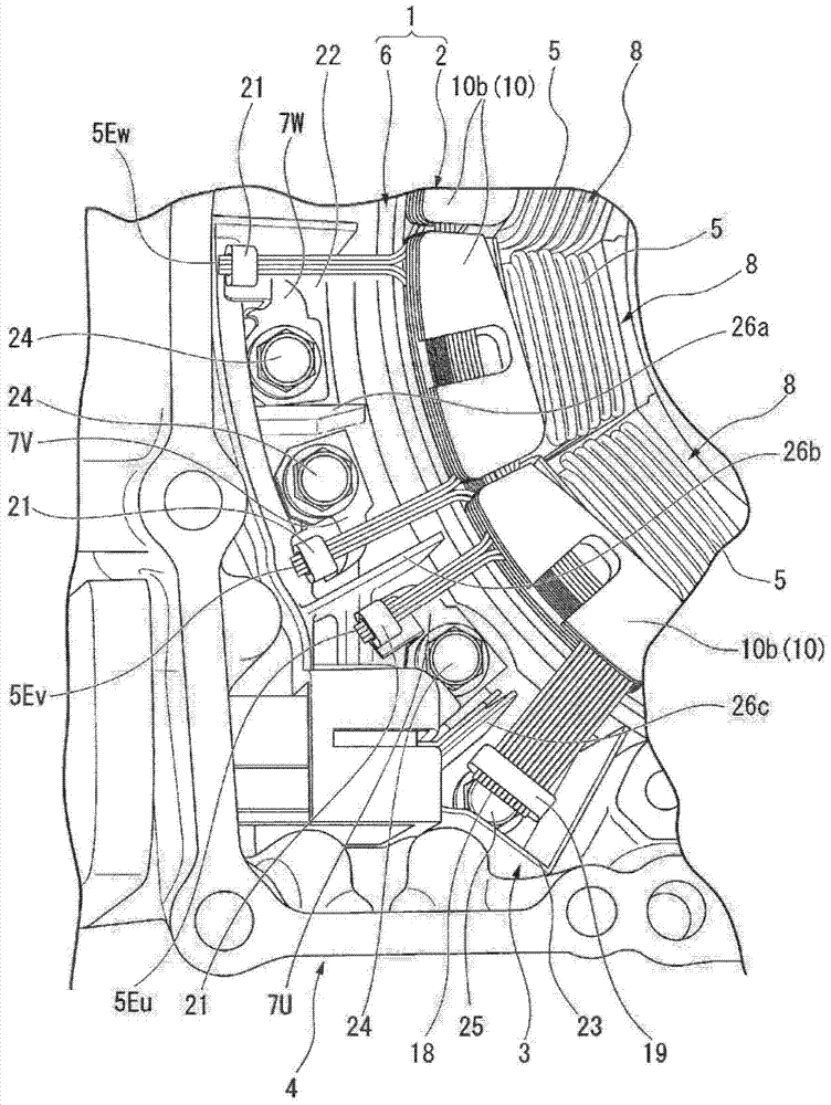
[0055] figure 1 It is a figure which shows the stator 1 incorporated in the electric rotating machine of this embodiment. figure 2 It is a figure which shows the single body of the stator core 2 of the stator 1. image 3 It is a figure which shows the state which assembled the stator 1 and the terminal block 3 in the case 4.

[0056] The rotating electrical machine of this embodiment is a three-phase AC type rotating electrical machine used for vehicle drive and regenerative power generation of an electric vehicle or a hybrid vehicle, and a rotatable rotor (not shown) is disposed inside an annular stator 1 . . The rotor is coupled to an axle of the vehicle via a reduction mechanism or the like.

[0057] The stator 1 includes: an annular stator core 2 on which a plurality of coil wires 5 are attached in salient-pole concentrated w...


PUM


Abstract

In the present invention, a rotary electric machine has a stator core formed by arranging in a circular shape a plurality of divided core pieces around which coil guide wires are wound, one end of each of the coil guide wires wound around each of the divided core pieces being connected to a corresponding phase power supply terminal, and the other ends of the respective coil guide wires being connected to each other as a neutral point. Each of the coil guide wires is formed from a rectangular wire. The end sections on the neutral point side of the respective coil guide wires are led out of a stator core from a single location on the circumference of the stator core. The end sections on the neutral point side form a mid-point connection section where the flat surfaces of the rectangular wires are in contact with each other, and the adjacent rectangular wires are physically joined and are all electrically connected to each other.

Description

technical field [0001] The present invention relates to a rotating electrical machine used for driving a vehicle or regenerative power generation, and more particularly to a rotating electrical machine in which a plurality of coil wires are wound around an annular stator core. [0002] this application claims priority based on Japanese Patent Application No. 2011-255217 for which it applied to Japan on November 22, 2011, and uses the content here. Background technique [0003] In a rotating electric machine used for vehicle driving or regenerative power generation, in order to facilitate the winding operation of the coil wire and improve the space factor, there is known a technique in which the stator core is composed of a plurality of divided coil pieces (for example, refer to Patent No. Literature 1). [0004] Patent Document 1 discloses a rotating electrical machine in which a coil wire is wound on each split core piece, the split core pieces around which the coil wire i...

Claims


Application Information

Patent Timeline
Patent Type & Authority Applications(China)
IPC IPC(8): H02K3/12H02K3/46H02K3/52
CPCH02K3/28H02K3/522H02K2203/06H02K2203/12
Inventor 矢崎学小野浩一山田贤源田太朗
Owner HONDA MOTOR CO LTD
Why Eureka
Try Eureka