Punching die of rear suspension installation bracket

A technology of mounting bracket and rear suspension, which is applied in the field of punching dies, can solve problems such as difficulty in ensuring the positioning size, difficulty in installing and positioning the rear suspension mounting bracket, and inapplicability of the rear suspension mounting bracket, so as to ensure performance and avoid Clogging, reducing the effect of repair rate

Active Publication Date: 2014-07-30
芜湖中瑞汽车零部件有限公司
View PDF7 Cites 5 Cited by
  • Summary
  • Abstract
  • Description
  • Claims
  • Application Information

AI Technical Summary

Problems solved by technology

The mold has a simple and reasonable structural design, fast opening and closing speed of the stamping die, high processing efficiency, compact structural design, small size, and is convenient for mold installation and management, but the mold is not suitable for rear suspension mounting brackets. The reason is that the structural characteristics of the rear suspension support and the rear suspension mounting bracket are different, and the parts that need to be punched are different, and the positioning of the rear suspension support is relatively simple. This mold can meet the positioning requirements, and the installation of the rear suspension mounting bracket Positioning is difficult, and the positioning size is difficult to guarantee

Method used


Image

  • Punching die of rear suspension installation bracket
  • Punching die of rear suspension installation bracket
  • Punching die of rear suspension installation bracket

Examples


Embodiment Construction

[0017] In order to make the technical means, creative features, objectives and effects of the present invention easy to understand, the present invention will be further explained below.

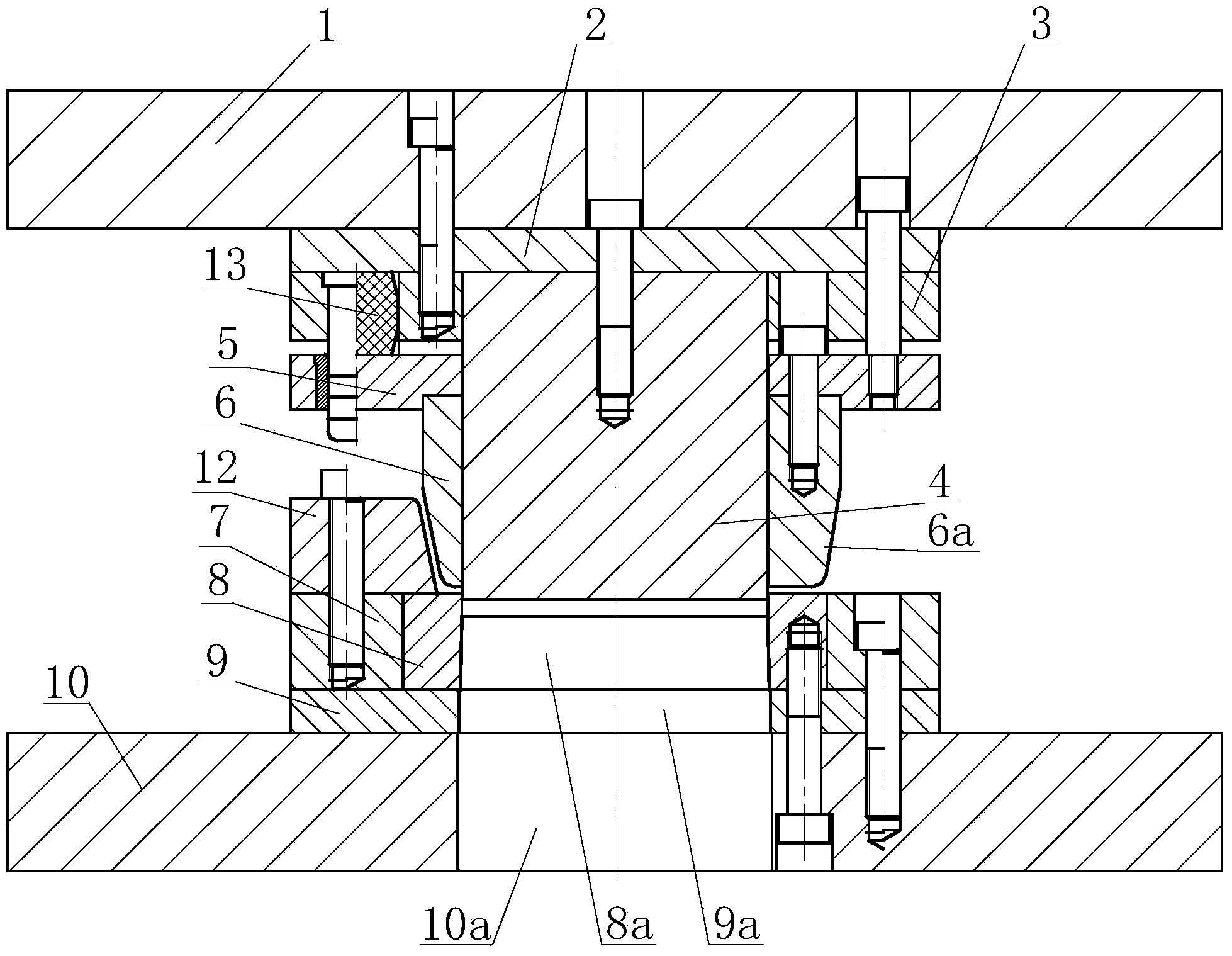
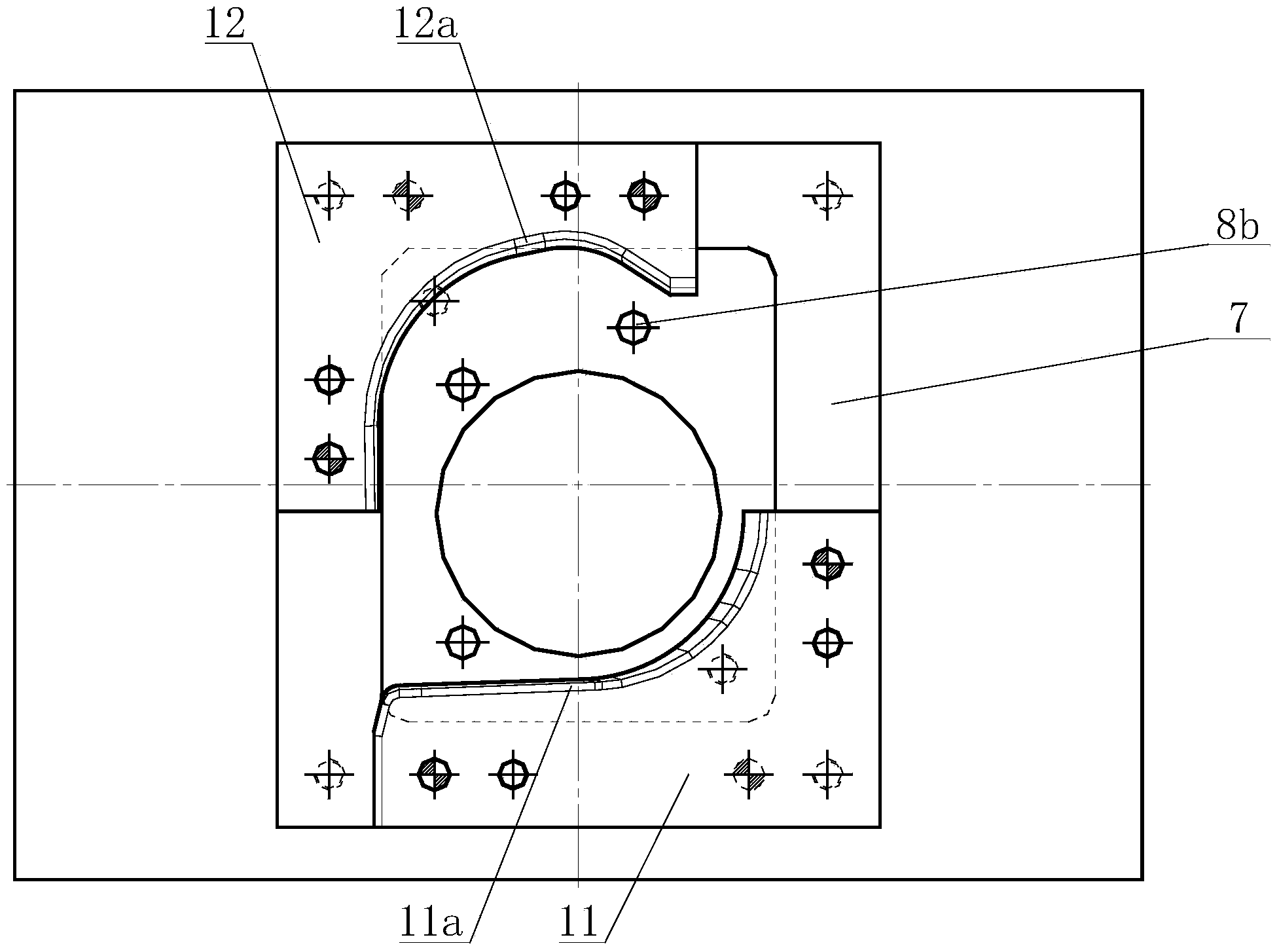
[0018] Such as Figure 1 to Figure 3 As shown, a punching die for a rear suspension mounting bracket includes an upper die and a lower die. The upper die includes an upper template 1, an upper backing plate 2, an upper fixing plate 3, a punch 4, a pressing plate 5 and The male mold 6, the lower mold includes a female mold insert 7, a female mold 8, a lower backing plate 9, a lower template 10, a right L-shaped positioning block 11 and a left L-shaped positioning block 12, and the lower backing plate 9 is fixedly connected Above the lower template 10, the die insert 7, the die 8 are fixed above the lower backing plate 9, the upper backing plate 2 is fixed below the upper formwork 1, the upper fixing plate 3 is fixed to the upper backing plate Below 2, the left side of the upper fixing plate 3 i...


PUM


Abstract

The invention relates to a punching die of a rear suspension installation bracket. The punching die comprises an upper die and a lower die, wherein the upper die comprises an upper die plate, an upper padding plate, an upper fixing plate, a punching head, a pressing plate and a male die, the lower die comprises a female die insert, a female die, a lower padding plate, a lower die plate, a right L-shaped locating block and a left L-shaped locating block, an elastic element is embedded in the left side of the upper fixing plate, the lower end of the elastic element is connected with the pressing plate, the punching head is clamped in the middle part of the upper fixing plate and the pressing plate, the upper end of the male die is fixedly connected with the middle lower part of the pressing plate, the lower end of the punching head penetrates through the male die, the female die is installed in the female die insert, the left L-shaped locating block is fixed at the left rear part of the upper part of the male die and the male die insert, and the right L-shaped locating block is fixed at the right front part of the upper part of the male die and the male die insert. The punching die of the rear suspension installation bracket has the advantages of reasonable structure design, convenience in control, high punching efficiency and the like, and the locating size of a to-be-punched part is guaranteed, so that the repair rate is reduced, the part is automatically separated, and convenience is provided for the use of an operator.

Description

Technical field [0001] The invention relates to the technical field of automobile spare parts processing, in particular to a punching die for a rear suspension mounting bracket. Background technique [0002] The structural features of the rear suspension mounting bracket commonly used in automobiles include a mounting surface and a side stop. The middle of the mounting surface needs to be punched to be used for positioning and connection with other parts of the car. When the existing punching die is used to punch holes, the punching process is performed after the flanging of the side baffle, and the structural features of the side baffle are not convenient for lateral positioning, and positioning errors are likely to occur, resulting in punching. The dimensional accuracy of the outlet hole is poor, which affects the installation and use of the rear mounting bracket. The position of the hole needs to be revised repeatedly to meet the requirements of use. The repair rate is relativ...

Claims


Application Information

Patent Timeline
Patent Type & Authority Applications(China)
IPC IPC(8): B21D28/34B21D43/00B21D45/08
Inventor 熊亚军陈伟方本家
Owner 芜湖中瑞汽车零部件有限公司
Why Eureka
Try Eureka