
Mechanical horizontal type broaching machine

A horizontal and mechanical technology, applied in the field of broaching machines, can solve the problems of high labor cost and management cost, unstable machining accuracy, high hydraulic oil cost, and achieve the effects of high production efficiency, convenient operation and reduced consumption.

Inactive Publication Date: 2014-07-30
ZHEJIANG CHR INTELLIGENT EQUIP
View PDF7 Cites 5 Cited by
  • Summary
  • Abstract
  • Description
  • Claims
  • Application Information

AI Technical Summary

Problems solved by technology

[0003] 1. For milling, each milling machine must be operated by a skilled miller, which results in high labor and management costs;
[0004] 2. Milling requires multiple clamping to mill multiple planes, and the machining accuracy is unstable;
[0005] 3. In terms of processing efficiency, a milling machine must be operated by a skilled miller, and the production efficiency is low
The main power source of the hydraulic horizontal tile broaching machine is controlled by hydraulic oil. The hydraulic oil required for a 5T-10T broaching machine is injected into about 1000L at a time, and it must be replaced regularly in the future, and the cost of hydraulic oil is high.

Method used


Image

  • Mechanical horizontal type broaching machine
  • Mechanical horizontal type broaching machine

Examples


Embodiment Construction

[0016] The present invention will be further described in detail below in conjunction with the accompanying drawings and embodiments.

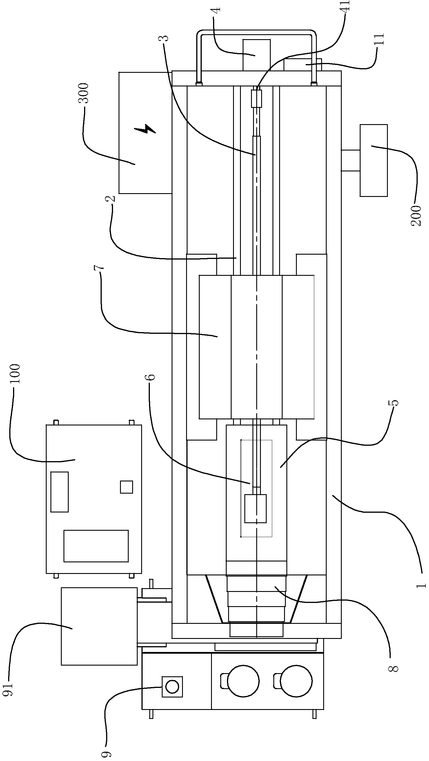
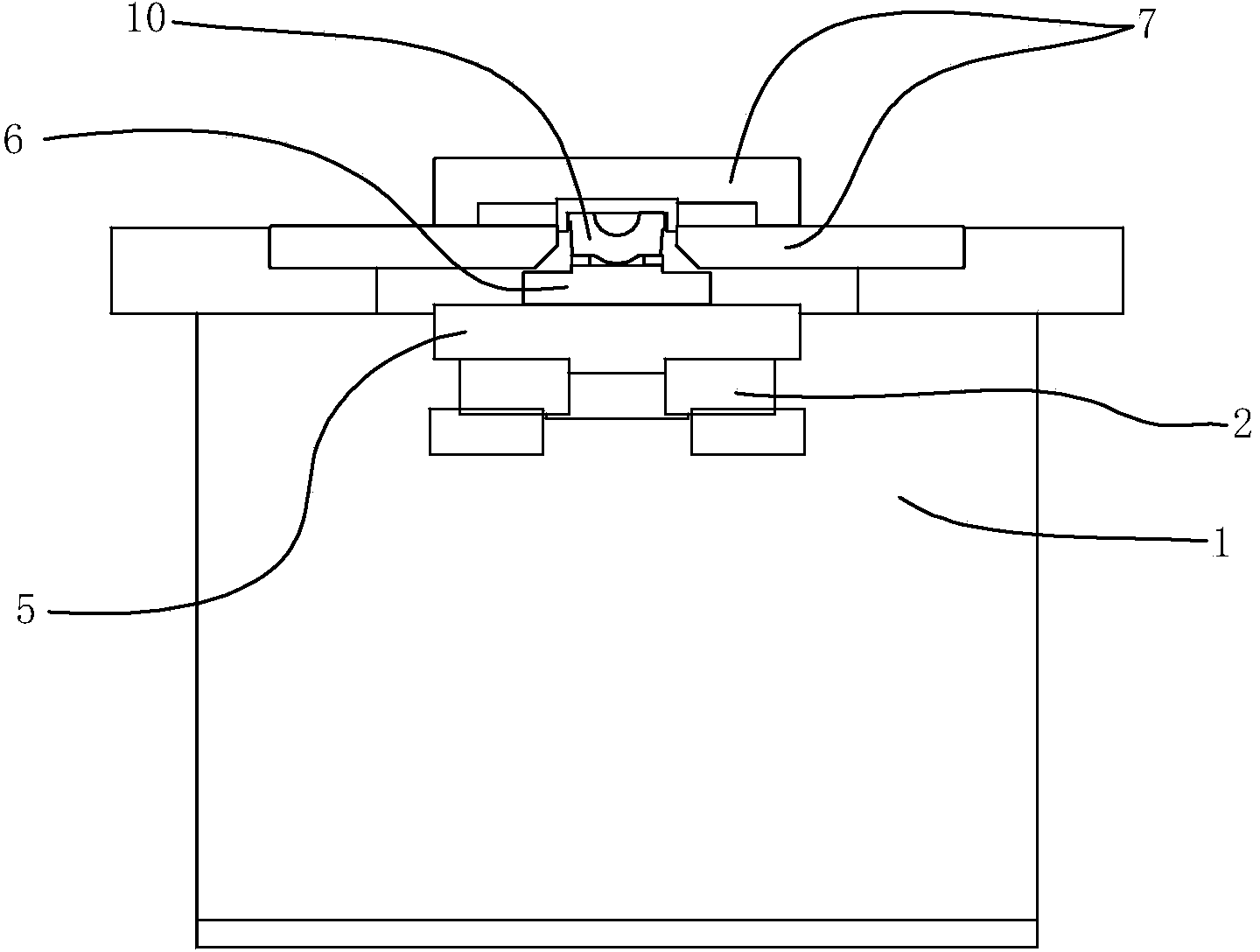
[0017] Such as Figure 1-2 As shown, the mechanical horizontal broaching machine of the present invention includes a horizontally arranged machine tool main body 1, and at least two parallel and spaced linear guide rails 2 arranged horizontally on the machine tool main body 1, and the linear guide rails 2 are also provided with The linear guide rail 2 extends in the same direction as the ball screw pair 3 , and the machine tool body 1 is also provided with a servo motor 4 that drives the ball screw pair 3 to move. Preferably, the servo motor 4 is fixed on the machine tool body 1 on one end side of the linear guide rail 2 and the ball screw pair 3, and the output shaft of the servo motor 4 is connected to the ball screw pair 3 through a coupling 41 to drive Ball screw pair movement.

[0018] The main slide 5 is connected above the ball screw ...


PUM


Abstract

The invention discloses a mechanical horizontal type broaching machine which comprises a horizontally arranged machine body and at least two linear guide tracks which are positioned on the machine body and extend in the horizontal direction at an interval, wherein ball screw rod pairs which extended in the same direction with the linear guide tracks are arranged between the linear guide tracks; a driving device for driving the ball screw rod pairs to move is further arranged on the machine body; a main sliding plate is connected to the ball screw rod pairs and the upper parts of the linear guide tracks; the main sliding plate moves along the linear guide tracks under the driving of the ball screw rod pairs; a clamp for clamping a workpiece is fixed on the main sliding plate; a broaching cutter is fixed on the machine body and is positioned above the clamped workpiece and / or on at least one of the left and right sides of the clamped workpiece. The mechanical horizontal type broaching machine disclosed by the invention is used for broaching in a mode that the broaching cutter is fixed and the workpiece moves, and the broaching cutter adopts a combination mode and can be adjusted according to workpieces to be machined, so that a servodrive is stable, the positioning is accurate, and the consumption of hydraulic oil is greatly reduced; moreover, precise broaching machining on a plurality of surfaces can be completed at one time, and the production efficiency is extremely high.

Description

technical field [0001] The invention relates to a broaching machine, in particular to a mechanical horizontal broaching machine. Background technique [0002] Tile parts are one of the important components of the automobile brake part. With the rapid development of the automobile industry, the requirements for the processing equipment of automobile parts are also getting higher and higher. The traditional processing technology of each plane of tile cover generally adopts milling technology. Usually milling process processing tile cover has the following disadvantages: [0003] 1. For milling, each milling machine must be operated by a skilled miller, which results in high labor and management costs; [0004] 2. Milling requires multiple clamping to mill multiple planes, and the machining accuracy is unstable; [0005] 3. In terms of processing efficiency, a milling machine must be operated by a skilled miller, and the production efficiency is low. [0006] Therefore, com...

Claims


Application Information

Patent Timeline
Patent Type & Authority Applications(China)
IPC IPC(8): B23D37/02B23D41/06B23D41/08B23Q5/40B23Q5/36B23Q11/08B23Q11/00
Inventor 林绿高
Owner ZHEJIANG CHR INTELLIGENT EQUIP
Learn More