Load-shedding type rigid culvert structure

A culvert and rigid technology, applied in the field of load-reducing rigid culvert structures, can solve problems such as difficult to realize, time-consuming and labor-intensive, and require high construction technology, and achieve the effect of reducing the maximum bending moment and reducing the soil pressure on the top of the culvert

Inactive Publication Date: 2014-07-30
CHINA UNIV OF GEOSCIENCES (WUHAN)
View PDF5 Cites 22 Cited by
  • Summary
  • Abstract
  • Description
  • Claims
  • Application Information

AI Technical Summary

Problems solved by technology

At present, there are many load reduction measures for culverts. Some load reduction measures have high requirements for construction technology, are time-consuming and laborious, and are difficult to implem...

Method used


Image

  • Load-shedding type rigid culvert structure
  • Load-shedding type rigid culvert structure
  • Load-shedding type rigid culvert structure

Examples


Embodiment 1

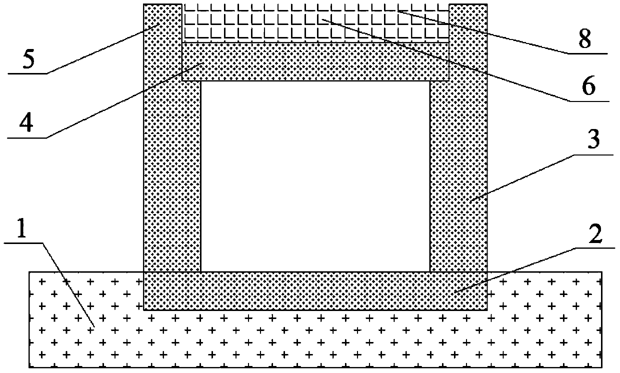
[0028] Such as figure 1 As shown, a load-reducing rigid culvert structure, the culvert is a cover culvert, including the foundation 2, the culvert side wall 3 and the culvert roof 4, and also includes a load-reducing block 5 and a load-reducing hole 6, and the load-reducing hole 6 filled with lightweight flexible material 8;

[0029] The foundation, the side wall of the culvert, the load-reducing block and the roof of the culvert are all reinforced concrete or plain concrete.

[0030] The load reducing block 5 is located directly above the top of the side wall 3 of the culvert, and is an integral structure with the side wall 3 of the culvert;

[0031] The length and width of the load-reducing block are consistent with the side wall of the culvert directly below it;

[0032] The load reduction hole 6 is located directly above the culvert roof 4 and is an open cavity surrounded by the culvert roof 4 and two load reduction blocks 5;

[0033] The depth of the load reduction hol...

Embodiment 2

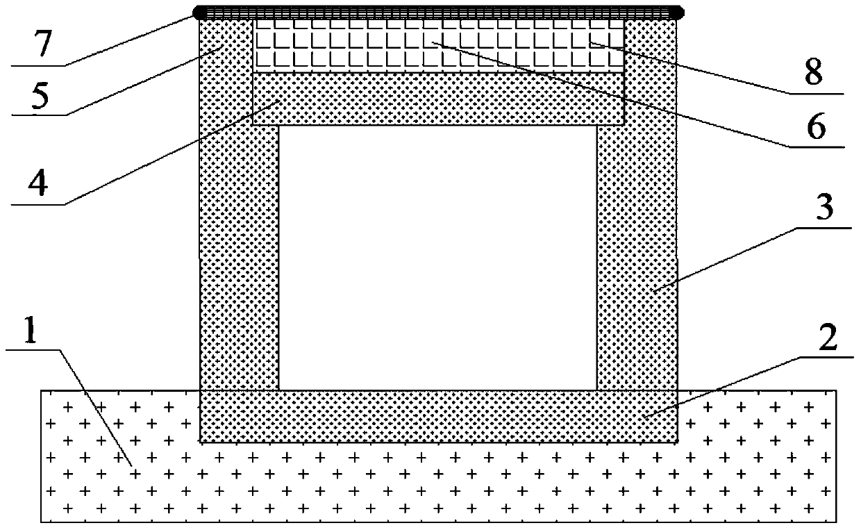
[0048] Such as figure 2As shown, a load-reducing rigid culvert structure, the culvert structure is mainly on the basis of embodiment 1, and additional reinforcements are laid. After the light flexible material 8 fills the load-reducing hole 6, a layer of reinforcement 7 is laid above the load-reduction hole, and the two sides of the reinforcement 7 are anchored on the outer edge of the top of the load-reduction block 5. It is not less than 1200kN / m, and it should be paved straight when laying; due to the increase of the tension film effect of the reinforcement, the upper part of the culvert side wall 3 is subjected to a pulling force that shrinks inward, so that the maximum bending moment on the culvert side wall 3 is reduced. Small, effectively reducing the impact of embankment fill on the force and deformation characteristics of the culvert side wall 3. In addition, the reinforcement material 7 produces deflection deformation under the action of the filling load, and the r...


PUM

PropertyMeasurementUnit
Densityaaaaaaaaaa
Elastic modulusaaaaaaaaaa

Abstract

The invention relates to the technical field of geotechnical engineering and road engineering, and particularly discloses a load-shedding type rigid culvert structure, which comprises a foundation, culvert side walls, a culvert top plate, load-shedding blocks and load-shedding holes, wherein the load-shedding blocks are positioned just above the culvert side walls, and form an integral structure together with the culvert side walls, the load-shedding holes are positioned between the two load-shedding blocks just above a culvert, and the interior of each load-shedding hole is filled with light-weight flexible material. The culvert structure has the advantages that after the structure is adopted, the construction and operation are easy and convenient, and the implementation is easy; the pressure of soil at the top of the culvert is obviously reduced, and the problem of cracking of the culvert is effectively solved; one part of load at the top of the culvert is transferred into the surrounding soil through the soil arch effect at the top of the culvert, the other part of load is transferred to the foundation through the culvert side walls, and then the vertical compressive capability of the culvert side walls is fully realized; the maximum bending moment of the culvert side walls is effectively reduced, and the stress distribution of the culvert is more reasonable; the stress asymmetry of the culvert is effectively reduced, and the separation and cracking of the connecting part of the top of the culvert and the side wall are avoided; the load-shedding effect is obviously improved.

Description

technical field [0001] The invention relates to the technical fields of geotechnical engineering and road engineering, in particular to a load-reducing rigid culvert structure. Background technique [0002] The thickness of covering soil on highway culverts is generally high, especially on high-fill road sections of mountainous expressways. Due to the large filling load, and the complex topography and geological conditions in some areas, the stress and deformation characteristics of culverts are often complex, and there are problems such as stress concentration in culverts and uneven settlement of structures, which are likely to cause problems of various degrees. In engineering circles, there is a saying of "ten culverts and nine cracks". These diseases can cause cracking, leakage or water accumulation in the culvert, and cause damage to the culvert structure, or even collapse, seriously affecting the normal use of the road. [0003] In order to reduce the earth pressure o...

Claims


Application Information

Patent Timeline
IPC IPC(8): E01F5/00
Inventor 陈保国宋丁豹焦俊杰
Owner CHINA UNIV OF GEOSCIENCES (WUHAN)
Why Eureka
Try Eureka