Upper turbine lower vortex hole driving rotary spraying device for ocean drilling platform pile shoe assistant lifting

An offshore drilling platform and pile shoe technology, which is applied in the valve device, valve operation/release device, lift valve and other directions, can solve the problem that the seabed sediment adsorption cannot be quickly relieved, the spraying area is small, and the rapid spraying and lifting cannot be achieved. effect and other issues, to achieve the effect of shortening the transfer period of the work area, improving the spraying effect, and accelerating the lifting.

Inactive Publication Date: 2014-07-30
庞维晓
View PDF5 Cites 0 Cited by
  • Summary
  • Abstract
  • Description
  • Claims
  • Application Information

AI Technical Summary

Problems solved by technology

[0002] The direction of the water column ejected by the jetting head of the jetting device in the prior art is fixed, so the action range of the jetting sediment is distributed in a point line, a

Method used


Image

  • Upper turbine lower vortex hole driving rotary spraying device for ocean drilling platform pile shoe assistant lifting
  • Upper turbine lower vortex hole driving rotary spraying device for ocean drilling platform pile shoe assistant lifting
  • Upper turbine lower vortex hole driving rotary spraying device for ocean drilling platform pile shoe assistant lifting

Examples


Embodiment

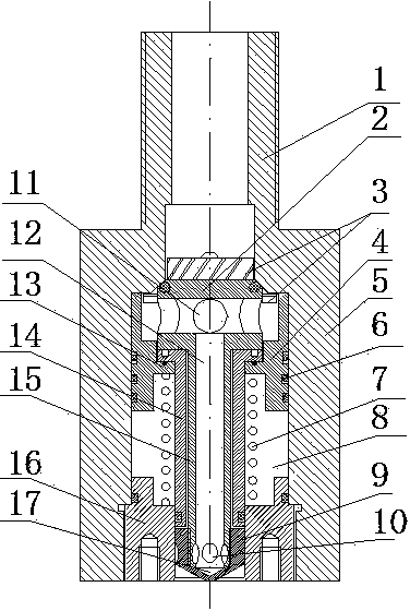
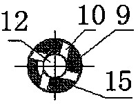
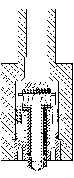
[0015] The spray flushing device working process of the present invention is as follows:

[0016] High-pressure water enters from the interface pipe, pushes the rotary valve core to move down, and the rotary valve core moves down in conjunction with the annular piston. During the downward movement of the annular piston, the high-pressure water drives the turbine blades to rotate, and at the same time drives the rotary valve core to rotate as a whole. The downward movement drives the spray punch at the lower end of the valve stem to extend downwards from the end cover, and the horizontal spray hole is opened to implement spray flushing and cleaning operations. When the high-pressure water of the interface pipe is closed, the annular piston resets under the action of the return spring, and the spray punch at the lower end of the ring valve stem retracts upwards into the middle hole of the end cover, the horizontal spray hole is closed, and the spray flushing and cleaning operatio...


PUM


Abstract

The invention provides an upper turbine lower vortex hole driving rotary spraying device for ocean drilling platform pile shoe assistant lifting. The structure comprises a shell body, an annular piston, a rotating valve core, a valve rod sleeve, an end cover and a reset spring, wherein a valve cavity is formed in the middle of the shell body, a connection pipe is arranged at the upper end of the shell body, the pipe cavity of the connection pipe is communicated with the valve cavity, the end cover is in thread connection onto the lower end of the valve cavity, a through hole is vertically formed in the center of the end cover, the annular piston 4 is arranged in the middle of the valve cavity, a concave ring is arranged in the middle hole of the annular piston, the upper part of the concave ring is connected with the turning edge at the upper end of the valve rod sleeve, the lower end of the valve rod sleeve is inserted into the central through hole in the end cover, the rotating valve core is formed by a turbine head, a valve rod and a spraying and washing head, the longitudinal section of the rotating valve core is T-shaped, the turbine head is arranged at the top of the valve rod, the spraying and washing head is arranged at the lower end of the valve rod, a horizontal through hole is formed in the turbine head, turbine blades are arranged above the horizontal through hole, a vertical through hole formed in the center of the valve rod is communicated with the horizontal through hole in the turbine head, and the valve rod is inserted into the valve rod sleeve and is connected with the valve rod sleeve in a sliding mode.

Description

technical field [0001] The invention relates to the technical field of offshore oil drilling platforms, in particular to an upper turbine and lower vortex hole driven swirling device for spud shoe lifting of the offshore drilling platform. Background technique [0002] The direction of the water column sprayed out by the jetting head of the jetting device in the prior art is fixed, so the action range of the jetting sediment is distributed in a point line, and the jetting area is small, and it is impossible to quickly remove the adsorption of the seabed sediment on the outer surface of the spud can. Can not reach the best rapid spraying and boosting effect. Contents of the invention [0003] The technical task of the present invention is to solve the deficiencies of the prior art, and provide an upper turbine and lower vortex hole driven swirling device for spud shoe lifting of an offshore drilling platform. [0004] The technical solution of the present invention is real...

Claims


Application Information

Patent Timeline
IPC IPC(8): E02D13/08F16K1/00F16K1/36F16K31/12
Inventor 齐宝兰
Owner 庞维晓
Why Eureka
Try Eureka