Composite material boom section for concrete pump truck boom

A technology for concrete pump trucks and composite materials, which is applied in the processing of building materials, construction, building construction, etc., and can solve the problems of poor anti-vibration performance of concrete pump truck booms, low effective bearing capacity of concrete pump trucks, and increasing the number of concrete pump trucks. Chassis load and other issues, to achieve the effect of safe, easy to implement, and strong design adaptability for the manipulator to work at heights

Active Publication Date: 2016-01-20
AEROSPACE RES INST OF MATERIAL & PROCESSING TECH +1
View PDF9 Cites 0 Cited by
  • Summary
  • Abstract
  • Description
  • Claims
  • Application Information

AI Technical Summary

Problems solved by technology

In the prior art, steel is generally used as the boom frame. The disadvantages are: (1) the boom itself has a large structural weight, which increases the load on the chassis of the concrete pump truck, and the effective bearing capacity of the concrete pump truck is low; (2) the boom The heavy weight of its own structure is unfavorable to the anti-vibration performance of the boom of the concrete pump truck; (3) During the long-term operation, the metal fatigue performance is lower than that of the composite material
The characteristic is that the skeleton of the boom section made of composite material is a hollow tubular structure. This molding technology requires a simple structure due to the need for demoulding operability, which limits the designability of the structure and size of the boom section in certain directions.
CN201010524111.4 adopts hot pressing forming process, the forming process is complicated, and the production process cost is high

Method used


Image

  • Composite material boom section for concrete pump truck boom
  • Composite material boom section for concrete pump truck boom
  • Composite material boom section for concrete pump truck boom

Examples


Embodiment Construction

[0029] Below in conjunction with accompanying drawing and specific embodiment the present invention will be described in further detail:

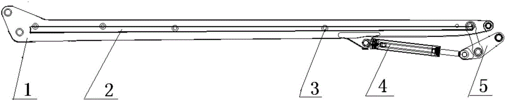
[0030] Such as Figure 5 Shown is a schematic diagram of the boom structure of the concrete pump truck. It can be seen from the figure that the boom frame of the concrete pump truck is composed of multiple boom sections connected end to end in turn. Figure 5 The fourth boom section in is described as an example.

[0031] Such as figure 1 Shown is a structural schematic diagram of the concrete pump truck arm section related to the present invention. The composite boom section consists of a skeleton 1, a concrete delivery pipeline 2, a connecting bolt 3, a hydraulic mechanism 4 and a connecting pin 5; the skeleton 1 includes a large end joint at one end, a main body at the middle and a Small end connector;

[0032] The concrete delivery pipeline 2 is fixed on the side of the main body of the skeleton 1 through the connecting bolt 3; one ...


PUM


Abstract

The invention relates to a composite material cantilever section for a cantilever crane of a concrete pump truck and a manufacturing method of the composite material cantilever section for the cantilever crane of the concrete pump truck, and belongs to the technical field of concrete pump trucks. The composite material cantilever section comprises a framework, a concrete conveying pipeline, a connecting bolt, a hydraulic mechanism and a connecting pin shaft, wherein the framework comprises a large end connector located at one end, a main body located in the middle part, and a small end connector located at the other end. The composite material cantilever section for the cantilever crane of the concrete pump truck is stronger in design adaptability, and a higher structure effect is acquired with lower quality cost to the greatest extent through the changes of the designable composite material, structure size and process.

Description

technical field [0001] The invention relates to a composite material arm section for a concrete pump truck arm frame and a manufacturing method thereof, belonging to the technical field of concrete pump trucks. Background technique [0002] Concrete pump truck is a special machine for conveying and pouring concrete. It can continuously convey concrete along the pipeline to the pouring site, and gradually becomes an indispensable key equipment in building construction. At present, the pump truck boom commonly used in the market is generally composed of 4-arm sections to 6-arm sections connected end-to-end in sequence. The structural diagram of the concrete pump truck boom is composed of 5 arm sections connected end-to-end in sequence. Figure 5 As shown, the boom part stretches greatly during work, and it is a cantilever beam structure in mechanics, and the force is more complicated. [0003] The boom section for the concrete pump truck boom includes a boom section frame, a h...

Claims


Application Information

Patent Timeline
Patent Type & Authority Patents(China)
IPC IPC(8): E04G21/04B29C70/34
Inventor 王建昌张会杰宋世伟冷霜尤洁颜鸿斌游少雄许晓燕
Owner AEROSPACE RES INST OF MATERIAL & PROCESSING TECH
Why Eureka
Try Eureka