Eureka AIR delivers breakthrough ideas for toughest innovation challenges, trusted by R&D personnel around the world.

Self-closed valve for gas transmission pipeline

A transmission pipeline, self-closing technology, applied in the field of self-closing valves, can solve the problems of high production cost, inconvenient transportation and access of dangerous gases, hidden safety hazards, etc., and achieve the effect of simple structure

Inactive Publication Date: 2014-07-30
HENAN UNIVERSITY OF TECHNOLOGY
View PDF4 Cites 4 Cited by
  • Summary
  • Abstract
  • Description
  • Claims
  • Application Information

AI Technical Summary

Problems solved by technology

In real life, gas has become an essential energy source in people's daily life. Due to people's lack of knowledge about the safe use of these gases, and even the lack of awareness of safety precautions for the use of these dangerous gases, many unnecessary losses and accidents have been caused.
Especially when the gas is suddenly stopped, it often happens that the user does not close the valve in time or forgets to close the valve. When the normal gas supply is restored, it is easy to cause gas leakage accidents
[0003] At present, most of the existing gas delivery valves do not have the function of automatic closing after the gas is cut off, and the production cost is high, the installation is difficult, the closing effect is not good, and the reliability is poor. Some valves cannot adjust the opening and closing degree, and only have two states of open and closed. Defects have brought inconvenience and safety hazards to the transportation and use of gases, especially dangerous gases

Method used


Image

  • Self-closed valve for gas transmission pipeline
  • Self-closed valve for gas transmission pipeline
  • Self-closed valve for gas transmission pipeline

Examples


Embodiment Construction

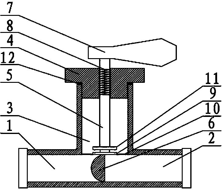
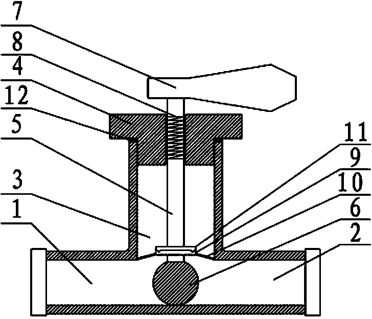
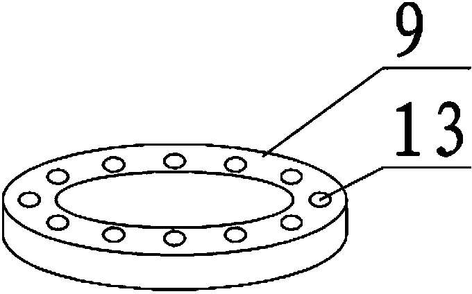
[0018] like Figure 1-4 As shown, the self-closing valve used in the gas delivery pipeline according to the present invention includes a valve body with a T-shaped structure composed of an inlet passage 1, an outlet passage 2 and a control chamber 3. On the upper part of the control chamber 3 A valve cover 4 is provided for sealing, and a sealing ring 12 is arranged on the joint surface of the valve cover 4 and the valve body; The valve core 6 of the hemispherical structure in 2 is fixedly connected; the upper end of the valve stem 5 placed outside the valve cover 4 is provided with a control handle 7; The two ends are respectively connected with the valve stem 5 and the valve cover 4; a positioning plate 9 is slid on the valve stem 5 close to the valve core 6, and the outer peripheral surface of the positioning plate 9 is sealed with the inner wall of the control chamber 3 through a stainless steel elastic ring film 10 Connection; the valve stem 5 above the positioning plate...


PUM


Abstract

The invention discloses a self-closed valve for a gas transmission pipeline. The self-closed valve comprises a valve body formed by an air inlet channel, an air outlet channel and a control cavity, and the valve body has a T-shaped structure; the upper part of the control cavity is provided with a valve cover in a sealing way; the lower end of a valve rod which extends into the control cavity from the center of the valve cover is fixedly connected with valve cores arranged in the air inlet channel and the air outlet channel; the upper end of the valve rod arranged outside the valve cover is provided with a control handle; a torsion spring is sheathed on the valve rod arranged in the valve cover; the two ends of the torsion spring are respectively connected with the valve rod and the valve cover; a locating plate is sheathed on the valve rod close to the valve cores in a sliding way; the peripheral surface of the locating plate is connected with the inner wall of the control cavity in a sealing way by an elastic ring film; limiting plates are fixedly arranged on the valve rod above the locating plate at intervals; locating pits and locating bosses arranged at the positions matched with those of the locating pits are respectively arranged on the surfaces where the locating plate is opposite to the limiting plates. The self-closed valve has the advantages of being simple in structure, and being capable of realizing the function of automatically closing after the gas is cut off.

Description

technical field [0001] The invention relates to valves, in particular to a self-closing valve used in gas delivery pipelines. Background technique [0002] The transportation of gas through pipelines is a common way in production and life. For example, the gas used in people's life is transported to thousands of households through pipelines, and some high-pressure and even dangerous gases are also transported through pipelines. In real life, gas has become an essential energy source in people's daily life. Due to people's lack of knowledge about the safe use of these gases, and even lack of awareness of safety precautions for the use of these dangerous gases, many unnecessary losses and accidents have been caused. Especially when the gas is suddenly stopped, it often happens that the user does not close the valve in time or forgets to close the valve. When the normal gas supply is restored, it is easy to cause a gas leakage accident. [0003] At present, most of the existi...

Claims


Application Information

Patent Timeline
Patent Type & Authority Applications(China)
IPC IPC(8): F16K17/04F16K17/168
CPCF16K17/164
Inventor 陈曦王军王海霞赵晴王海涛陈雁毕文峰刘恺
Owner HENAN UNIVERSITY OF TECHNOLOGY
Why Eureka
Eureka Blog
Learn More