
A Method for Calibrating Strapdown Inertial Combination Gyroscope Combination

A strapdown inertial and gyroscope technology, used in instruments, measuring devices, etc., can solve the problems of rough installation error angle results and low precision.

Active Publication Date: 2017-01-04
BEIJING INST OF AEROSPACE CONTROL DEVICES
View PDF5 Cites 0 Cited by
  • Summary
  • Abstract
  • Description
  • Claims
  • Application Information

AI Technical Summary

Problems solved by technology

However, in the previous calibration of the installation error angle, the quadratic term and cross-coupling term related to the angular velocity will be ignored, which will lead to a rough result of the calibrated installation error angle and low accuracy.

Method used


Image

  • A Method for Calibrating Strapdown Inertial Combination Gyroscope Combination
  • A Method for Calibrating Strapdown Inertial Combination Gyroscope Combination
  • A Method for Calibrating Strapdown Inertial Combination Gyroscope Combination

Examples


Embodiment Construction

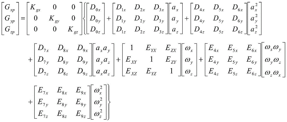
[0083] The combined error model of the strapdown inertial combined gyroscope is

[0084] G xp G yp G zp = K gx 0 0 0 K gy 0 ...


PUM


Abstract

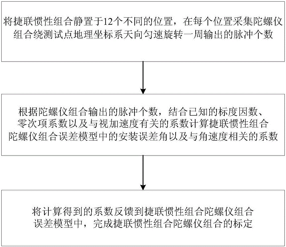
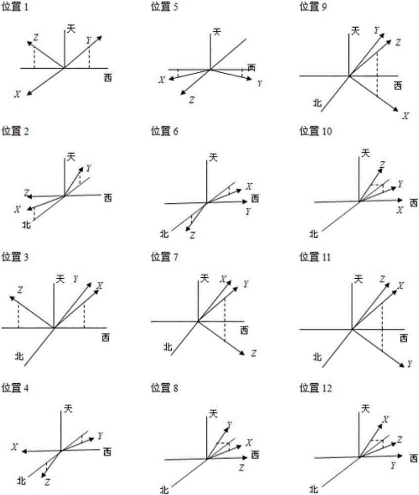
The invention discloses a method for calibrating a strapdown inertial combined gyroscope combinant. When scale factors of the gyroscope combinant and error coefficients related with accelerated speed are known, pulse output values acquired by rotating a strapdown inertial combinant by one circle at constant speed at 12 positions are sequentially acquired, and cross coupling coefficients and quadratic term coefficients which are related with angle speed in an error model of the strapdown inertial combined gyroscope combinant are calculated. Compared with other calibration methods of error coefficients, the calibration, including calibration of high-order errors, for error parameters, related to the angle speed, of the strapdown inertial combined gyroscope with three coordinate axes is finished, and therefore, the accuracy of the error model of the strapdown inertial combined gyroscope combinant is improved, and the calibration process is simple and the required time is short.

Description

technical field [0001] The invention relates to a method for calibrating a strapdown inertial combination gyroscope combination, in particular to a method for calibrating the error coefficient of a strapdown inertial combination gyroscope combination related to angular velocity, which belongs to the strapdown inertial combination calibration technology and can be used for calibrating a gyroscope Combined occasions. Background technique [0002] The gyroscope is the core component of the inertial system. It is used for the angular displacement or angular velocity of the sensitive carrier relative to the inertial space. It plays a key role in the performance of the inertial system and is one of the key contents of inertial technology research. In order to completely measure the angular velocity and angular displacement of the carrier in space, the strapdown inertial combination is equipped with three gyroscopes whose sensitive axes are perpendicular to each other, and the dire...

Claims


Application Information

Patent Timeline
IPC IPC(8): G01C25/00
CPCG01C25/005
Inventor 魏宗康刘璠彭智宏李念滨
Owner BEIJING INST OF AEROSPACE CONTROL DEVICES
Learn More