Moving imaging satellite attitude control method based on incremental type drift angle

An imaging satellite and attitude control technology, applied in the field of satellite attitude control, can solve the problems that the satellite does not consider the influence of roll and pitch angular velocity on the control, cannot meet the imaging requirements in motion, and the difference

Active Publication Date: 2014-07-30
BEIJING INST OF CONTROL ENG
View PDF5 Cites 17 Cited by
  • Summary
  • Abstract
  • Description
  • Claims
  • Application Information

AI Technical Summary

Problems solved by technology

However, since the satellite has an active rotational angular velocity in the roll and pitch directions, the attitude control method of the satellite during imaging in motion is quite different from that in the steady state
[0004] Traditional satellites only involve imaging when the attitude is stable, and the influence of roll and pitch angular velocity on the control is not considered in the yaw axis control process of the satellite, so it can no longer meet the higher imaging requirements in motion

Method used


Image

  • Moving imaging satellite attitude control method based on incremental type drift angle
  • Moving imaging satellite attitude control method based on incremental type drift angle
  • Moving imaging satellite attitude control method based on incremental type drift angle

Examples


Embodiment Construction

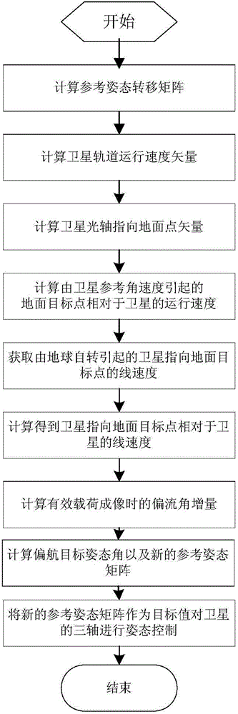
[0024] Such as figure 1 Shown, the inventive method mainly comprises the following steps:

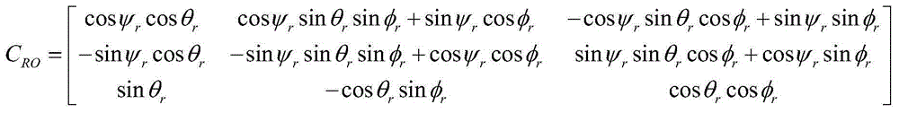
[0025] (1) During the imaging process of the satellite in motion, let the rolling target attitude angle of the satellite at the current moment be φ r , Pitch target angle θ r and yaw target attitude angle ψ r , to establish a reference attitude coordinate system. Among them, the conversion matrix between the reference attitude coordinate system and the orbit coordinate system is C RO to represent, among them

[0026] C RO = cos ψ r cos θ r cos ψ r sin θ r ...


PUM


Abstract

A moving imaging satellite attitude control method based on an incremental type drift angle is suitable for an attitude control process when initiative angular speeds of rotation exist in three axes in a satellite imaging process. All traditional satellite imaging satellite attitude control methods are only suitable for the situation that satellite rolling and pitch attitudes are close to zero. According to the method, when the drift angle is obtained, the current target attitude of a satellite is selected as the reference standard, an increment of the drift angle is obtained firstly in an obtaining process of the drift angle, the increment is formed relative to the drift angle of the satellite at the current moment, an updated reference attitude matrix serves as a target attitude matrix during attitude control, and therefore the satellite attitude can follow the target attitude. The method can not only meet the requirement for satellite attitude control of moving imaging but also be used for attitude control in an imaging process of the traditional satellite, so that satellite attitude control is more flexible.

Description

technical field [0001] The invention belongs to the field of satellite attitude control and relates to an attitude control method of an imaging satellite. Background technique [0002] Generally, when an earth observation satellite is imaging, its roll and pitch attitudes are in a stable state, that is, the angular velocity of the roll and pitch attitudes is close to zero. The satellite relies on the orbital speed to achieve push-broom for ground targets. direction parallel. In order to improve the imaging efficiency of satellites, or to achieve strip pushbrooms that are not parallel to the flight direction of satellites, satellites have gradually developed an imaging mode in motion. In the process of imaging in motion, the satellite will have an active push-broom angular velocity. At this time, the angular velocity of the satellite's roll and pitch attitude is no longer zero, and will change with time. [0003] When the satellite is imaging, it is necessary to correct the...

Claims


Application Information

Patent Timeline
IPC IPC(8): G05B17/00
Inventor 田科丰雷拥军宗红姚宁何海锋朱琦吕高见傅秀涛綦艳霞潘立鑫李晶心
Owner BEIJING INST OF CONTROL ENG
Why Eureka
Try Eureka