
Imaging-based guidance system for ophthalmic docking using a location-orientation analysis

A technology of imaging system and guidance system, used in ophthalmic surgery, application, medical science, etc.

Active Publication Date: 2014-07-30
ALCON INC +1
View PDF9 Cites 3 Cited by
  • Summary
  • Abstract
  • Description
  • Claims
  • Application Information

AI Technical Summary

Problems solved by technology

However, the use of such imaging systems can also be problematic

Method used


Image

  • Imaging-based guidance system for ophthalmic docking using a location-orientation analysis
  • Imaging-based guidance system for ophthalmic docking using a location-orientation analysis
  • Imaging-based guidance system for ophthalmic docking using a location-orientation analysis

Examples


Embodiment Construction

[0041] Implementations and embodiments in this patent document provide an imaging system that includes the ability to isolate and identify patient eye shift and tilt and present this shift and tilt information in an integrated and adaptive manner to avoid overloading the surgeon ophthalmic docking system. This docking system can help increase the accuracy and convenience of docking the patient interface of an eye surgery system, such as a laser cataract surgery system, with the eye.

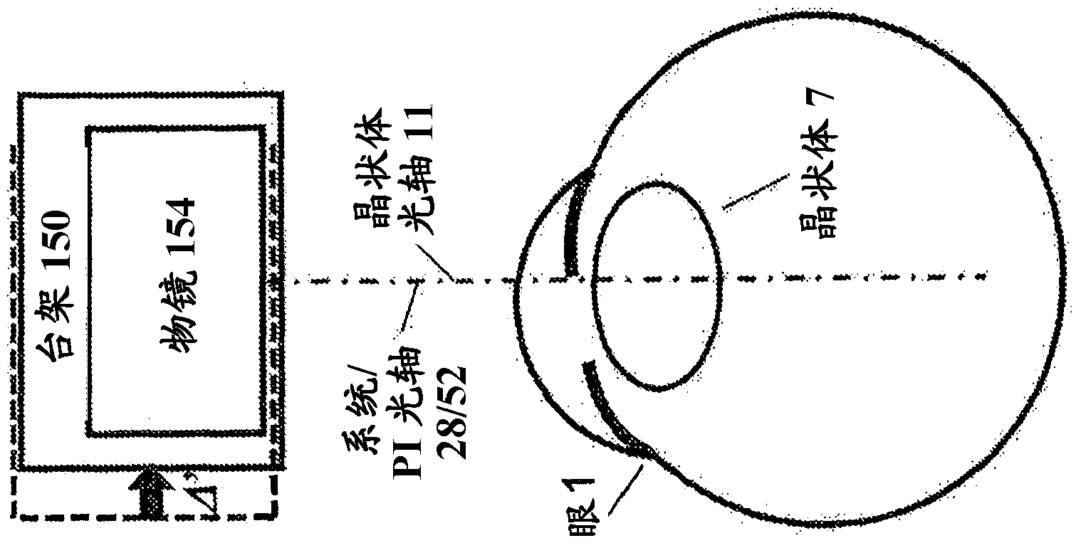
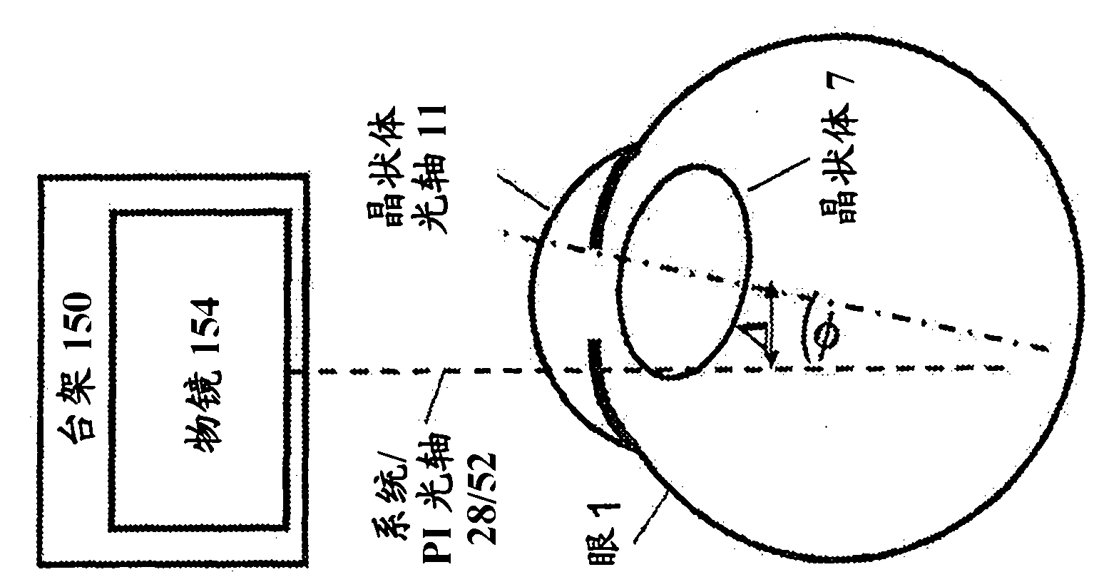
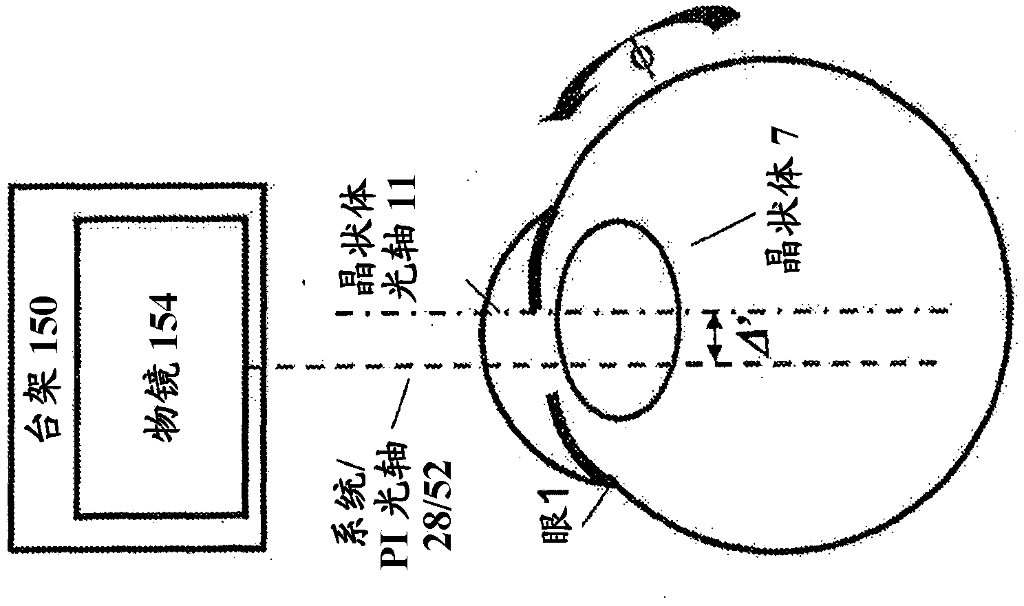
[0042] Figure 1A-1B Misalignment of the patient interface (PI) 50 with its PI contact lens 51 relative to the eye 1 is illustrated. Well-known structures in the eye 1 include the cornea 2 , the iris 3 , and the sclera 4 separated from the iris 3 by the limbus 5 . The opening of the iris 3 defines a pupil 6 . The lens 7 is the internal structure of the eye 1 and is held in place by the soft ciliary muscle 8 .

[0043] Figure 1A It is illustrated above that the lens 7 deviates from the optica...


PUM


Abstract

An imaging-guided docking system can separate the tilt and location of an imaged ophthalmic target and present them in an intuitive manner for an ophthalmic surgeon. The docking system can include an ophthalmic imaging system to image a portion of an eye of a patient, an image processor to determine a location and an orientation of the imaged portion of the eye, and a guidance system, coupled to the ophthalmic imaging system, to guide an ophthalmic docking based on the determined location and orientation. In some implementations, the imaging system images an internal eye-structure to determine its orientation and a video-imaging system video-images a frontal eye-structure to determine a location of the frontal eye-structure. The determined orientation and location can be displayed for the surgeon. The alignment of ophthalmic procedures can also be assisted with this imaging capability, e.g. the placement and centration of IOLs into the lens capsule.

Description

[0001] Cross References to Related Applications [0002] This application claims priority under 35 USC §119 to US Application Serial No. 13 / 218,628, filed August 26, 2011, the entire contents of which application are hereby incorporated by reference. technical field [0003] This patent document relates to systems and techniques for ophthalmic docking. More specifically, this patent document relates to systems and methods for providing an imaging-based guidance system based on position-orientation analysis for docking an ophthalmic system to a patient's eye. Background technique [0004] The widespread introduction and acceptance of laser surgery systems has ushered in a new era of precision and control for ophthalmic applications. One of the keys to achieving this high degree of control is the immobilization of the eye relative to the laser surgery system. In many devices, this immobilization is performed by securing the patient interface to the objective lens of the lase...

Claims


Application Information

Patent Timeline
IPC IPC(8): A61B3/14A61B3/15
CPCA61F9/008A61F2009/00851A61F2009/00887
Inventor A·朱阿兹I·戈德史利格
Owner ALCON INC
Learn More